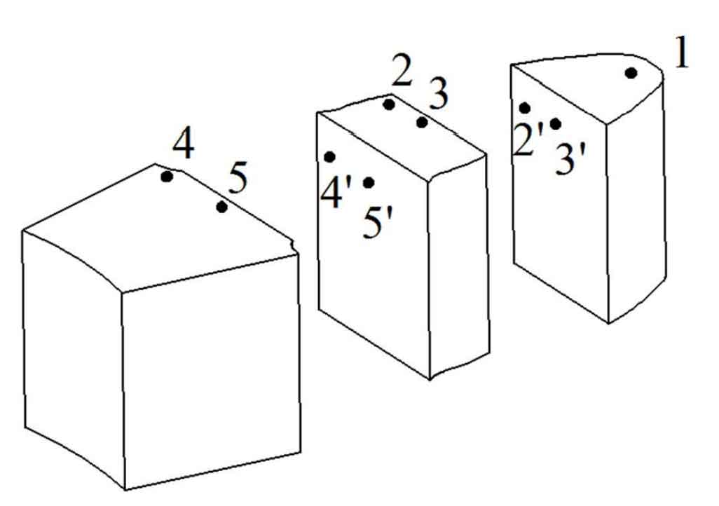
The microstructure of spur gear tooth profile is deformed by compound forming, and the grain shape and size are also changed. The equivalent strain at spur gear tooth profile characterizes the direction and degree of grain deformation.The composite formed spur gear parts are cut longitudinally and transversely to obtain the tooth shape sample as shown in Figure 1. Take the tooth profile indexing circle and tooth root circle as the benchmark for cutting, and observe the metallographic organization of tooth top 1, 2 ~ 3 of tooth profile surface and center at indexing circle, 4 ~ 5 of tooth profile surface and center at tooth root circle, 2 ‘~ 3’ of tooth profile longitudinal section at indexing circle and 4 ‘~ 5’ of tooth profile longitudinal section at tooth root circle respectively.
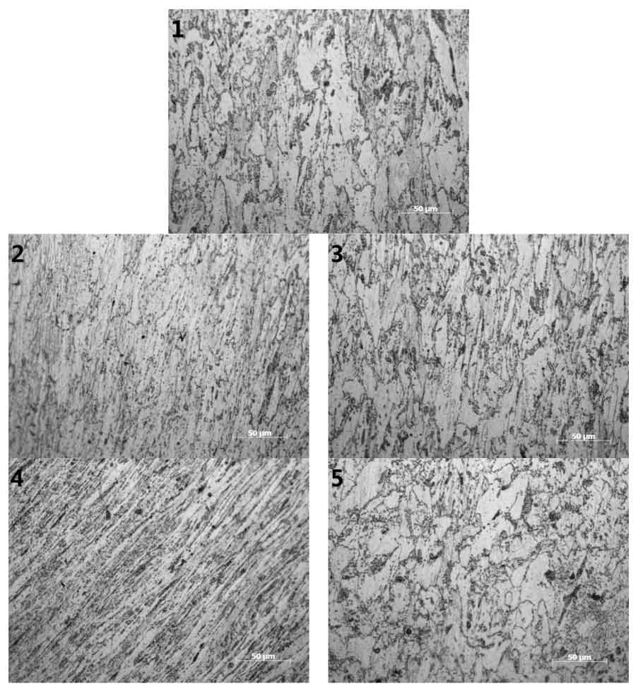
In order to observe the metallographic structure of each sampling point, the observation surface of each cut sample is polished and polished, and corroded with 4% nitric acid alcohol solution for about 20s, and observed with Carl Zeiss axiovert200 mat digital metallographic microscope. Fig. 2 is the microstructure diagram of the cross section of the composite formed spur gear. It can be seen from the microstructure of each region that the shape and size of metal grains have changed compared with the microstructure before extrusion.
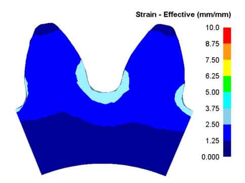
The ferrite grain size and shape of spur cylindrical gear tooth top part 1 change little, and spherical carbides gather at the ferrite grain boundary. This is because the metal deformation of tooth top part is the smallest in the composite forming process, as shown in Fig. 3, and the equivalent effect variation in tooth top part is the smallest.
The ferrite grains in the surface layer 2 of the tooth profile indexing circle of spur gear are gradually elongated along the involute direction. Although ferrite is deformed, some ferrite grain boundaries are still retained, some spherical carbides gather at the grain boundaries and some distribute along the deformation direction. The orientation of grains changed greatly, from disordered grains before deformation to in-situ upward order. The ferrite grains in the center 3 of the indexing circle change little, and the spherical carbides gather at the ferrite grain boundary. Although the ferrite is deformed, its grain boundary is complete. This is because the deformation of the core metal is smaller than that of the outer metal. As shown in Figure 3, the surface equivalent effect variable is greater than that of the core.
The ferrite grains in the surface layer 4 of the tooth root circle of spur cylindrical gear are broken, and the point granular carbides are distributed along the deformation direction. Due to the maximum equal effect change at the tooth root, the deformation is large, and the orientation of point granular carbides tends to be consistent. The deformation texture phenomenon is obvious here, so as to improve the bending fatigue life of the tooth root of the gear. Because the deformation of the root circle center is small in the composite forming process, the ferrite grain size and shape change at the root circle center 5 are small.
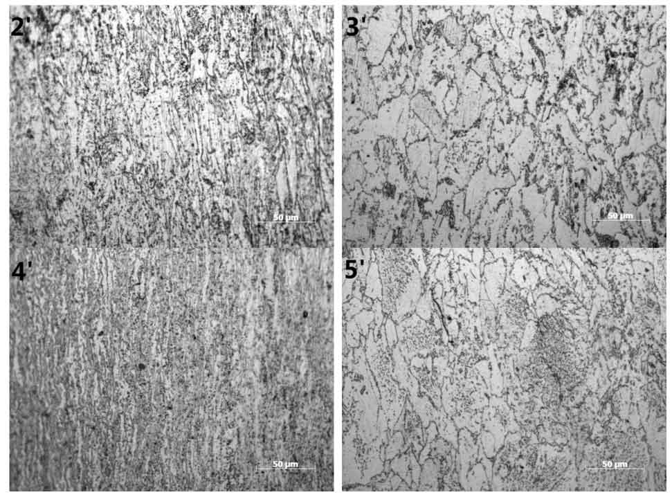
As the axial deformation of the metal is the main deformation direction in the extrusion process, the grain morphology of the longitudinal section of the surface metal will change. Fig. 4 is the microstructure diagram of the longitudinal section of the composite formed spur gear. In the figure, the ferrite grains on the surface of the tooth profile are elongated, the granular carbides are distributed in a streamline shape, and the streamline direction is parallel to the tooth profile surface. Because the deformation at the tooth root is greater than that at the indexing circle, the streamline density at the tooth root is greater than that at the indexing circle. The deformation of the core metal is small, only a small amount of ferrite grains are elongated, and granular carbides gather at the grain boundary, so there is almost no obvious streamline.
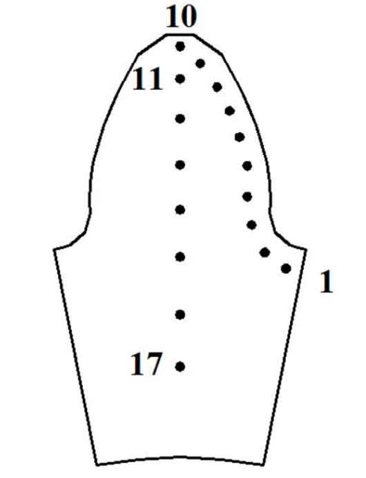
Cold deformation can increase dislocations in grains and enhance dislocation strengthening, so as to improve hardness. Taking the cross-sectional sample of spur gear as the hardness test sample, there are 3 test samples in total. The sample shall be ground and polished according to GB / t4340 1-2009 Vickers hardness test of metal materials, with a loading weight of 500g and a holding time of 10s. The test points are shown in Figure 5. A total of 17 points are selected from the involute tooth root to the tooth top and from the radial tooth top to the center.
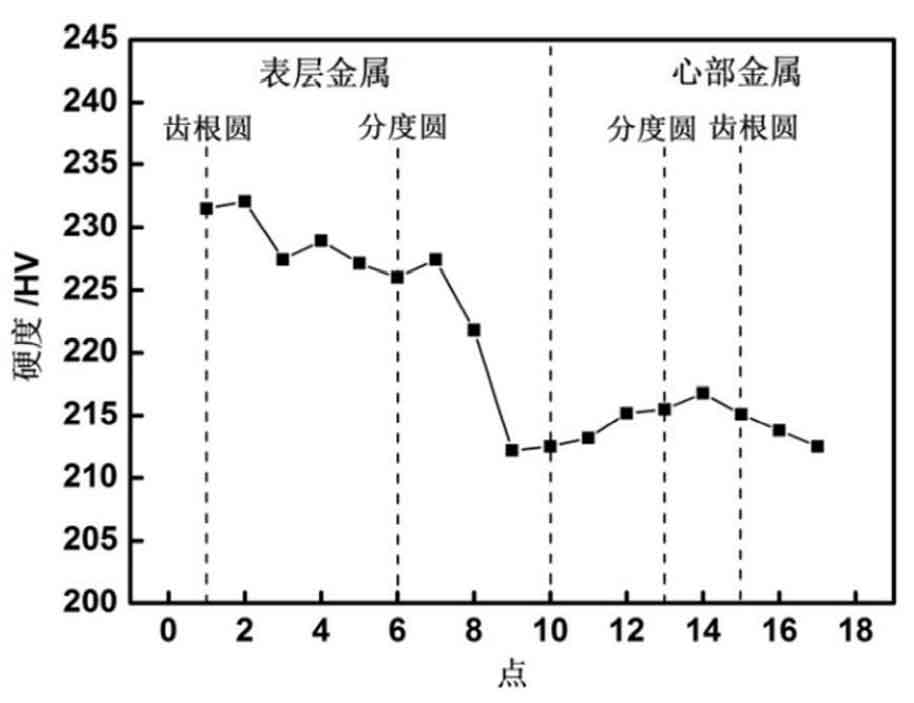
The average value of the three test data is taken as the Vickers hardness value of the composite formed spur gear, and Fig. 6 is the Vickers hardness distribution diagram of the composite formed spur gear. It can be seen from the figure that at the same position, the deformation of the surface metal is greater than that of the core metal, so the hardness of the surface metal is higher. For example, the Vickers hardness value of the surface metal of the tooth root circle is hv232, and the hardness of the core is only hv214. In the surface layer, the deformation degree of different parts is different, and their hardness is also different. The hardness increases with the increase of deformation degree. The deformation degree at the tooth root is the largest, so the hardness is the highest, the deformation degree at the tooth top of spur cylindrical gear is the smallest, and its hardness value is also the lowest. In the center, because the metal deformation is small, the hardness value is close, and the maximum value appears between the indexing circle and the tooth root circle.

