Introduction
Cylindrical gear transmission is the most widely used transmission method in power transmission mechanisms. The meshing characteristics of gear pairs will directly affect the transmission performance of mechanical equipment, and gear teeth are the key structure for transmitting motion and power in gear pairs. The geometric shape of gear teeth will directly affect the transmission performance of gear pairs. Currently, cylindrical gears mainly include spur cylindrical gears, helical cylindrical gears, herringbone cylindrical gears, and circular arc cylindrical gears. Although the existing processes and cutting methods of hobbing and hobbing have been continuously improved, they cannot achieve continuous gear machining with full tooth width, and the efficiency of gear machining is limited. The emergence of high-speed dry hobbing has to some extent improved the production efficiency and tooth surface integrity of gear machining, but its process parameters need to be further optimized and the cutting tools are prone to wear. In addition, due to processing, installation errors, and elastic deformation, gear pair meshing transmission is prone to biased loads, which affect the service life of the gears. Numerous scholars have conducted extensive research on circular arc tooth profile cylindrical gears and their machining methods Propose to use the rotating disc method to machine arc gears; Milling circular arc tooth profile cylindrical gears through five axis linkage CNC machine tools; Using the parallel connecting rod method to manufacture arc toothed cylindrical gears with ideal parameters; Propose the composite machining of single double-edged rotating milling cutter discs. However, the above processing methods require single tooth cutting, which results in low processing efficiency and limits the application of helical cylindrical gears. To improve the machining efficiency of cylindrical gears and the load-bearing capacity of gear pairs, a new type of planar helical profile cylindrical gear and its rapid prototyping method are proposed. This processing method uses a rotating large disk to quickly mill gears. Several tool holders and cutting tools are arranged on the disk according to a planar spiral line. The pitch of the planar spiral line is equal to the pitch of the processed gear, that is, S=π m, where S is the pitch of the planar spiral line and m is the modulus; When the cutterhead rotates once, the processed gear rotates one tooth, and the rotating cutterhead drives the tool to continuously cut different tooth grooves of the gear, which can quickly achieve continuous cutting of the full tooth width of the gear and improve the efficiency of gear processing. The processed gear is unfolded along the indexing cylindrical surface, and the tooth profile is a planar spiral (Archimedean spiral), so it is named a planar spiral tooth profile cylindrical gear.
Principle of machining planar helical profile cylindrical gears
At present, both the hobbing method and the hobbing method widely used for processing cylindrical gears cannot achieve continuous processing of the full tooth width of the gear. In order to improve the cutting efficiency of gears and achieve continuous cutting of gears with full tooth width, a cutting tool is now installed on the large cutting disc, with the distance between the tool axis and the center of the cutting disc being RT. Taking the machining of a gear rack as an example, when the cutterhead rotates at a high speed of ω D, the tool path is circular. If the gear rack is stationary radially on the cutterhead, it continuously feeds along the axial direction of the cutterhead, and the machined tooth groove is in the shape of a circular arc. The principle of machining circular arc tooth grooves is shown in Figure 1. This processing method requires the gear rack to be rotated radially along the cutter head after each tooth slot is processed, and then the next tooth slot is processed, greatly limiting the efficiency of gear processing.
The above processing method is improved. While the cutter head rotates, the rack moves in a straight line along the radial direction of the cutter head at a certain speed v. The principle of forming a spiral tooth line is shown in Figure 2. The spiral tooth line is the trajectory formed by the tool on the rack, and the relative motion of the tool to the rack is circular while moving in a straight line along the radial direction. Therefore, the trajectory formed by the tool on the rack is a planar spiral line (Archimedean spiral line) with a certain pitch.
1) Processing is divided into deep cutting processing and expansion processing. During deep cutting, the speed v of the gear rack movement is converted into the angular velocity ω C of the cylindrical workpiece. At the same time, due to the inability to complete tooth groove processing in one go, the gear blank needs to rotate along the cutter head while rotating Axial feed motion is performed, and the cylindrical gear blank rotates once to reprocess the already processed tooth groove, achieving deep cutting processing.
2) When generating machining, it is necessary to add rotational speed and linear motion along the radial direction of the cutting disc to the gear blank on the basis of the original motion relationship, that is, generating motion, which will be explained in detail in Section 1.3.
3) In order to achieve continuous processing, the tool is cut from the tooth blank and rotated once to cut into the tooth groove again. When the tool needs to cut the next tooth groove, the speed relationship is required to meet the requirement that the cutter head rotates once and the tooth blank rotates one tooth pitch,
Namely, ω C/ω D=1/Z, where Z is the number of gear teeth. At this point, when the tool rotates once and cuts in again from the upper end of the gear blank, the tool performs the next deep cutting of the tooth groove, which can achieve continuous processing.
Machining of planar helical cylindrical gears
The feasibility of the machining principle of planar helical profile cylindrical gears is demonstrated through gear simulation machining using VERICUT software. Based on the processing principle, models of the machining machine, rotating machining tool head, and gear blank are established in VERICUT software to simulate the machining of a planar helical profile cylindrical gear model. The machined tooth surface is compared and analyzed with the theoretical model, and the machining steps of the planar helical profile cylindrical gear are simulated. Gears and machining tools are modeled using SOLIDWORKS software to create gear blanks and machining tool heads. The tool heads and tools are imported into the VERICUT tool management library to create gear machining tool models. The angle between the gear machining tool and the cutting disc plane is 90 °, and the cutting edge rotates to form the principle of a cutting edge cylindrical surface.
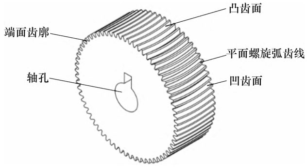
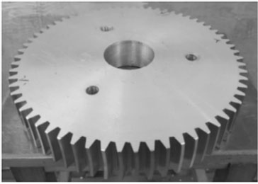
During the simulation process, there is no interference or collision, resulting in a cylindrical gear with a planar helical tooth profile. During the machining process, the cutter head continuously mills the gear, enabling continuous cutting of the entire tooth width. Simulated planar spiral tooth profile circle The tooth surface of a cylindrical gear is divided into concave and convex tooth surfaces, and the radius of the tooth line on the concave tooth surface is slightly larger than that on the convex tooth surface, forming a slightly thicker tooth at the centerline of the tooth width than at the end face, that is, a micro drum shaped tooth. The machining method of planar helical gear cylindrical gears and the simulation verification results of VERICUT software have been developed. A planar helical gear cylindrical gear machining machine tool has been developed, with a total of 6 front and rear through type tool slots on the machining disc for installing cutting tools. The machining disc is fixed to the machine tool by bolts. The through type groove is used to install cutting tools, which are positioned radially by threaded bolts. It is mainly used for fixing and controlling the position of the cutting tools radially. Multiple bolt holes are added on both sides of the through type cutting groove, matched with washers, mainly used for fixing the bolt rod to prevent the bolt rod from shaking and affecting the machining accuracy during rapid rotation processing. The physical object of the planar spiral tooth profile cylindrical gear is machined using customized special cutting tools made of hard alloy steel, which can achieve continuous cutting of the full tooth width of the gear. Its machining efficiency is significantly higher than that of the existing cylindrical gear hobbing.
The planar helical cylindrical gear has five main parameters, namely module m, number of teeth Z, pressure angle α, tooth width B, and helix curvature radius RT (installation radius of the main cutting tool) at the centerline of the tooth width. In order to clarify the geometric characteristics of planar helical cylindrical gears, based on the meshing relationship between gears and racks, the characteristics of planar helical cylindrical gears are analyzed through planar helical gear rack analysis. The forming principle of planar spiral arc gear is divided into left-handed and right-handed planar spiral arc gear according to the rotation direction of the planar spiral line. The principle of tooth surface forming is that the tooth profile of the middle section of a planar helical cylindrical gear is an involute tooth profile, and the tooth profile of the middle section of the gear is used as a reference. The other sections are twisted and offset by one position angle compared to the middle section. There is a slight asymmetry between the teeth on both sides of the tooth width centerline of a planar helical gear, similar to helical gears. When meshing, a pair of left-hand and right-hand planar helical gears with equal modulus, pressure angle, and helix curvature radius at the tooth width centerline are required for meshing.
Conclusion
For the first time, a method for continuous cutting of cylindrical gears with full tooth width using a large blade was proposed, and the feasibility of this method was verified through machining simulation using VERICUT software. The geometric characteristics of planar helical profile cylindrical gears were proposed and preliminarily analyzed, and the following conclusions were obtained.
1) Propose a method for continuous cutting of cylindrical gears with a wide tooth width using a large cutting disc. Several cutting tools are arranged in a planar spiral on the cutting disc to ensure that the pitch of the spiral is the same as the tooth pitch of the gear. During machining, the large cutting disc rotates once, and the workpiece rotates one tooth, achieving efficient continuous machining of the gear.
2) The middle tooth profile of a cylindrical gear with a planar spiral tooth profile is the standard involute, while the tooth profiles of other sections are approximately the standard involute; The tooth profile is a planar spiral, with a concave tooth surface arc radius RN and a convex tooth surface arc radius RN The tooth radius RW is related to RN-RW=π m/2.
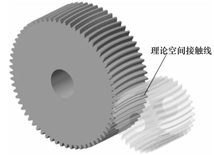
3) The theoretical tooth surface contact characteristics of the planar helical profile cylindrical gear pair are as follows: the contact interval is mainly distributed in the middle area of the contact tooth surface of the gear teeth, reducing the bending stress at the tooth roots at both ends of the gear teeth and improving
The load-bearing capacity of the gear pair. At present, research on planar helical profile cylindrical gears mainly focuses on analyzing the machining methods and geometric characteristics of the gears. Subsequently, it is necessary to calculate the tooth surface equation of the gear and analyze the distribution of tooth surface contact stress and tooth root bending stress of planar helical profile cylindrical gears; Simultaneously build a gear transmission experimental device to study the transmission characteristics of planar helical cylindrical gears.


