
I treat the development of machine-tool software for large spiral bevel gear manufacturing as a problem of coupling a complex kinematic process with a flexible numerical control platform. A spiral bevel gear is not a simple replacement for a cylindrical gear. Its tooth flanks are generated by a combination of cutter rotation, workpiece rotation, and several spatial offsets. The contact pattern, transmission error, and surface finish are extremely sensitive to small changes in tool setting, machine setting, and servo response. In my work, I focused on building an application layer for the iTNC530 control system so that a large special machine for spiral bevel gear production can be operated through a structured human-machine interface rather than through raw general-purpose NC programming.
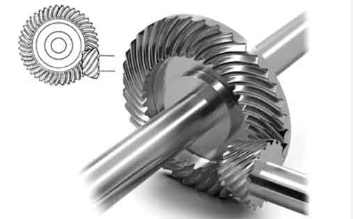
The main reason for this development is that a general CNC system, even a powerful one, does not automatically provide the complete process logic for a spiral bevel gear. The machine can move, interpolate, and compensate, but the operator still needs a process-oriented environment for gear parameters, cutter parameters, machine settings, and process settings. My objective was to create a software layer that reduces programming effort, lowers the risk of incorrect settings, supports simulation, provides tooth contact analysis, and enables servo optimization for the actual cutting conditions of a spiral bevel gear.
1. Technical Background and Motivation
A spiral bevel gear offers high overlap ratio, strong load capacity, high transmission ratio, high transmission efficiency, smooth motion, and low noise. These properties make the spiral bevel gear important in vehicles, aviation, mining machinery, ships, and drilling platforms. However, the same geometry that gives the spiral bevel gear its advantages also makes it difficult to manufacture. The tooth surface is a spatial curved surface, and the relative motion between cutter and workpiece is more complex than in most ordinary milling operations.
In many production environments, large spiral bevel gear machining still depends on special machines or imported equipment. The machine itself is only one part of the solution. The software interface determines how easily the operator can configure the process, check the program, simulate the cut, analyze contact, and optimize the servo system. I therefore divided my development work into four practical modules:
| Module | Purpose | Main Benefit for Spiral Bevel Gear Production |
|---|---|---|
| Gear machining | Collect gear, cutter, machine, and process parameters and generate CYCLE-based programs | Reduces manual NC editing and prevents parameter confusion |
| Three-dimensional simulation | Check tool path, undercut, overcut, and collision before cutting | Protects the spiral bevel gear blank and cutter head |
| Tooth contact analysis | Evaluate contact path, contact ellipse, and transmission error | Improves meshing quality before physical cutting |
| Online optimization | Support servo and process tuning | Improves surface finish, accuracy, and stability during spiral bevel gear cutting |
My design principle was not to replace the iTNC530 kernel. Instead, I used the open interfaces of the control system to add a process-specific layer. This layer appears as softkeys, pages, CYCLE dialogs, and PLC-based interactions. The operator still works inside a familiar Heidenhain-style environment, but the content of that environment is dedicated to the spiral bevel gear process.
2. Spiral Bevel Gear Classification and Machining Methods
A spiral bevel gear can be classified in several ways. According to the relative position of the gear pair axes, I consider three main families:
| Axis Relationship | Description | Typical Use |
|---|---|---|
| Perpendicular intersecting | Axes intersect at 90 degrees | Common bevel gear drives |
| Non-perpendicular intersecting | Axes intersect but the angle is not 90 degrees | Special transmission layouts |
| Offset axes | Axes do not intersect and have a hypoid offset | Hypoid spiral bevel gear drives |
According to the tooth line, the two most important forms in my work are the circular-arc tooth and the cycloid tooth. A circular-arc spiral bevel gear is usually cut by a circular face milling cutter. A cycloid spiral bevel gear is usually cut by a face milling cutter head with inner and outer blades, and the tooth line is related to an extended epicycloid.
The machining method determines how the tooth flank is generated. In my software design, I grouped the common methods as follows:
| Method | Basic Principle | Software Consideration |
|---|---|---|
| Forming method | The cutter profile corresponds closely to the tooth space shape | Indexing and depth control are critical |
| Generating method | The cutter and workpiece roll relative to each other like a meshing gear pair | Requires coupled rotary axes and precise synchronization |
| Modified roll method | The generating motion is modified to improve contact | Needs additional motion coefficients |
| Cutter tilt method | The cutter axis is tilted to control pressure angle and contact | Needs accurate machine setting parameters |
For a spiral bevel gear, the gear ratio and pitch cone angles can be written as:
$$ i = \frac{z_2}{z_1} = \frac{d_2}{d_1} $$
$$ \tan \delta_1 = \frac{\sin \Sigma}{i + \cos \Sigma} $$
$$ \delta_2 = \Sigma – \delta_1 $$
Here, \(z_1\) and \(z_2\) are the pinion and gear tooth numbers, \(d_1\) and \(d_2\) are the pitch diameters, \(\Sigma\) is the shaft angle, and \(\delta_1\) and \(\delta_2\) are the pitch cone angles. For a spiral bevel gear, the spiral angle is also a defining parameter. If the cutter radius is \(r_0\) and the cone distance is \(R\), a simplified relation is:
$$ \beta = \arcsin\left(\frac{r_0}{R}\right) $$
The tooth height system can be summarized by:
$$ h_a = m(1 + X_r) $$
$$ h_f = h – h_a $$
where \(h_a\) is the addendum, \(h_f\) is the dedendum, \(h\) is the whole tooth height, \(m\) is the module, and \(X_r\) is the radial modification coefficient. These equations are embedded in my parameter pages so that the operator can see the consequence of changing a basic spiral bevel gear parameter.
3. Parameter Classification for the Spiral Bevel Gear Process
I divided the parameters used in actual spiral bevel gear machining into four groups. This classification is the backbone of the interface. It prevents the operator from mixing design data, cutter data, machine data, and process data. Each group is represented by a set of Q parameters, and each group is exposed on a dedicated CYCLE page.
3.1 Gear Parameters
| Q Code | Parameter | Meaning |
|---|---|---|
| Q1 | \(z_1\) | Pinion tooth number |
| Q2 | \(z_2\) | Gear tooth number |
| Q3 | \(d_1\) | Pinion pitch diameter |
| Q4 | \(d_2\) | Gear pitch diameter |
| Q5 | \(\delta_1\) | Pinion pitch cone angle |
| Q6 | \(\delta_2\) | Gear pitch cone angle |
| Q7 | \(\alpha\) | Pressure angle |
| Q8 | \(\beta_0\) | Spiral angle |
| Q9 | \(h_a\) | Addendum |
| Q10 | \(h\) | Whole tooth height |
| Q11 | \(X_r\) | Radial modification coefficient |
| Q12 | \(X_t\) | Tangential modification coefficient |
| Q13 | Hand of spiral | Right-hand or left-hand configuration |
3.2 Tool Parameters
| Q Code | Parameter | Meaning |
|---|---|---|
| Q31 | \(r_0\) | Theoretical cutter head radius |
| Q32 | \(r_t\) | Cutting radius |
| Q33 | \(z_p\) | Number of cutter blade groups |
| Q34 | \(\alpha_{t1}\) | Outer blade inclination angle |
| Q35 | \(\alpha_{t2}\) | Inner blade inclination angle |
| Q37 | \(\alpha_{tx}\) | Outer blade inclination angle in working coordinates |
| Q38 | \(\Delta \alpha_{tx}\) | Blade rotation angle |
| Q47 | Root generating start angle | Controls root contact development |
| Q48 | Tip generating start angle | Controls tip contact development |
| Q49 | \(h_f\) | Dedendum height |
3.3 Machine Parameters
| Q Code | Parameter | Meaning |
|---|---|---|
| Q21 | Distance from cutter tip plane to A axis | Defines machine spatial reference |
| Q22 | Height from cutter tip plane to table | Used when cutter points downward and Z is zero |
| Q23 | Height from gear crossing point to table | Establishes vertical workpiece position |
| Q24 | \(S\) | Radial cutter position |
| Q25 | \(q\) | Angular cutter position |
| Q26 | \(z_w\) | Generating wheel tooth number |
| Q27 | \(\phi_{w0}\) | Cycloid start angle |
| Q28 | \(r_p\) | Cycloid rolling circle radius |
| Q29 | Generating tip start angle | Used for modified generating motion |
| Q49 | \(d_t\) | Cycloid deflection angle |
3.4 Process Parameters
| Q Code | Parameter | Meaning |
|---|---|---|
| Q40 | Safety distance | Clearance before cutting |
| Q41 | \(C\) axis initial angle | Initial angular position for tooth cutting |
| Q42 | Start tooth number | First tooth to be machined |
| Q43 | Generating segments in tooth height direction | Controls depth subdivision |
| Q44 | Segments in tooth length direction | Controls length subdivision |
| Q45 | \(\Delta \phi_{ws}\) | Machining start angle |
| Q46 | \(\Delta \phi_{we}\) | Machining end angle |
| Q47 | Root generating start angle | Root contact control |
| Q48 | Tip generating start angle | Tip contact control |
| Q49 | \(h_f\) | Dedendum height |
By placing these four groups into separate CYCLE dialogs, I made the spiral bevel gear programming process more transparent. The operator does not need to remember a long calculation card. The software accepts the essential inputs, stores them in Q parameters, and calls the appropriate machining cycle.
4. Machine Platform and CNC Architecture
The target machine is a large special machining center with six axes. Three axes are linear, \(X\), \(Y\), and \(Z\), and three axes are rotary, \(A\), \(B\), and \(C\). The machine is designed for five-axis simultaneous operation. A spiral bevel gear blank can be clamped once and then machined through several operations. The machine structure is intended to support turning, milling, boring, drilling, and tapping, but my software work concentrates on the spiral bevel gear cutting function.
| Axis | Control Type | Travel or Range | Accuracy |
|---|---|---|---|
| X | Closed loop | 2000 mm | 0.020 mm |
| Y | Closed loop | 1700 mm | 0.020 mm |
| Z | Closed loop | 1000 mm | 0.016 mm |
| A | Closed loop | 90 degrees | 0.0001 degree |
| B | Closed loop | 360 degrees | 0.0001 degree |
| C | Closed loop | 360 degrees | 0.0001 degree |
The control system is an iTNC530. I selected this platform because it provides short block processing time, short control loop periods, linear and circular interpolation, helical interpolation, spline interpolation, and jerk control. These features matter for a spiral bevel gear because the generating motion must be smooth and synchronized. Any servo lag or abrupt acceleration change can appear directly on the tooth flank.
The iTNC530 also offers a structured PLC environment. I used the PLC layer for machine-specific logic such as axis clamping, lubrication, cooling, tool change support, error messages, and softkey handling. The PLC basic program provides many ready-made functions, so I could adapt existing structures instead of writing every function from zero.
| Control Feature | Value for Spiral Bevel Gear Machining |
|---|---|
| Short block processing time | Supports dense tool path points |
| Short control loop period | Improves synchronization of rotary axes |
| Jerk control | Reduces shock and vibration on the tooth surface |
| Standard CYCLE support | Enables reusable process dialogs |
| PLC softkeys | Enables custom operator pages |
| Integrated oscilloscope | Supports servo tuning and diagnosis |
5. Human-Machine Interface Architecture
I designed the human-machine interface as a page set rather than as a single screen. The main page gives access to the four functional modules plus help, file management, and exit. Each module has its own subpages and CYCLE dialogs. The interface uses the same visual language as the original control system so that the operator does not need to learn a completely new environment.
| Page or Function | Operator Action | Result |
|---|---|---|
| Main page | Select gear machining, simulation, TCA, optimization, help, file, or exit | Enters the required module |
| Gear machining | Create a new file or call an existing file | Prepares the spiral bevel gear program |
| Parameter pages | Input gear, cutter, machine, and process parameters | Stores values in Q parameters |
| Method pages | Select forming, generating, modified roll, or cutter tilt | Adds the correct machining cycle |
| Simulation page | Run a test simulation | Verifies path and collision state |
| TCA page | Compute contact pattern and transmission error | Evaluates meshing quality |
| Optimization page | Adjust servo parameters | Improves dynamic response |
The communication between the application layer and the control kernel follows the available system interfaces. The operator input from the MDI keyboard or the display softkeys is processed by the control data module. Machine-specific data exchange is handled through serial and Ethernet interfaces, and the PLC layer manages the machine-side signals. Feedback from the machine is returned to the LCD screen so that the operator can observe the state of the spiral bevel gear process.
6. Development Methods for the Interface
I used two development routes. The first route is Python-based and uses PyQt, QtDesigner, and PyCharm. The second route uses the manufacturer’s own engineering tools. Both routes can produce a working page set, but they differ in speed, flexibility, and maintenance effort.
6.1 Python and PyQt Route
In the Python route, I first designed the page in QtDesigner. The result is a .ui file, which is an XML description of the interface. I then used pyuic to convert the .ui file into a .py file. After that, I added the application framework, signal-slot connections, bitmap handling, and calls to PLC variables or NC macros.
A typical application skeleton contains an import section, a main window class, a setup function, a translation function, and an event loop. The important part for my spiral bevel gear software is that each softkey must be connected to a function. For example, the gear machining button opens the file selection page, the simulation button opens the test-run page, and the TCA button opens the contact analysis page.
| Step | Tool | Output | Role in Spiral Bevel Gear Software |
|---|---|---|---|
| Page design | QtDesigner | .ui file | Layout of gear, cutter, machine, and process pages |
| Conversion | pyuic | .py file | Python representation of the interface |
| Editing | PyCharm | Executable GUI code | Signal handling and process logic |
| Integration | PLC and NC macros | Control-accessible functions | Reads and writes Q parameters |
The Python route is flexible. It can create complex widgets, tables, and dynamic pages. However, it has a longer development cycle. When the spiral bevel gear process changes, I often need to edit the Python source, rebuild the interface, and test the communication again.
6.2 Manufacturer Tool Route
The second route uses PLCdesign NT, BMXdesign, PLCtext, MenuDesign, and CycleDesign. This route is more direct for a machine-tool OEM because the tools are already aligned with the control structure. I can create a softkey tree, assign bitmaps, define CYCLE dialogs, generate text files, and upload the result to the control.
| Tool | Function | Use in My Spiral Bevel Gear Interface |
|---|---|---|
| PLCdesign NT | PLC programming and project management | Softkey logic, machine signals, error handling |
| BMXdesign | Bitmap and softkey graphics | Icons for gear, cutter, machine, and process pages |
| PLCtext | Text and error message database | Operator messages for parameter and process errors |
| MenuDesign | PLC softkey tree | Custom menu structure for the spiral bevel gear module |
| CycleDesign | CYCLE creation and softkey integration | Gear, cutter, machine, and process CYCLE dialogs |
The manufacturer tool route is easier to maintain. If a new spiral bevel gear method is required, I can add a new CYCLE page and a new softkey branch without rewriting the whole interface. The developed tree can then be uploaded to the control through Ethernet or serial transfer. For this reason, I used this route for the final integration of the gear machining module and kept the Python route for prototyping and auxiliary functions.
7. Gear Machining Module
The gear machining module is the core of the spiral bevel gear software. It guides the operator from file creation to program generation. The flow is:
| Step | Operator Input | Software Action |
|---|---|---|
| 1 | Create or call file | Initializes parameter memory |
| 2 | Select tooth system | Chooses circular-arc or cycloid spiral bevel gear |
| 3 | Input gear parameters | Writes Q1 to Q13 |
| 4 | Input cutter parameters | Writes Q31 to Q49 |
| 5 | Input machine parameters | Writes Q21 to Q29 |
| 6 | Input process parameters | Writes Q40 to Q49 |
| 7 | Select machining method | Adds forming, generating, modified roll, or cutter tilt cycle |
| 8 | Run simulation | Checks path and interference |
| 9 | Execute dry run | Confirms machine motion |
| 10 | Execute continuous machining | Cuts the spiral bevel gear |
The generating motion can be expressed in a simplified form. If the generating wheel rotates by \(\phi_w\), the workpiece rotation \(\phi_c\) is related by the ratio of the generating wheel tooth number \(z_w\) to the workpiece tooth number \(z\):
$$ \phi_c = \frac{z_w}{z} \phi_w $$
The cutter position in the machine plane can be described by radial and angular components:
$$ x = S \cos q $$
$$ y = S \sin q $$
When modified roll is used, the angular position is not a simple linear function of the generating angle. I represent it as a polynomial correction:
$$ q(\phi_w) = q_0 + c_1 \phi_w + c_2 \phi_w^2 + c_3 \phi_w^3 $$
These coefficients are entered on the process page. They allow the operator to tune the contact pattern of the spiral bevel gear without changing the basic gear geometry.
8. Three-Dimensional Simulation Module
Before cutting a large spiral bevel gear, I need to be sure that the program is correct. A collision between the cutter head and the workpiece, fixture, or machine table can cause expensive damage. The simulation module therefore performs a virtual test run. It checks the tool path, the blank removal volume, and the distance between moving components.
| View Mode | Description | Benefit |
|---|---|---|
| Plane view | Fast two-dimensional display of the path | Quick check of gross errors |
| Three-plane projection | Top, front, and side projection | Comparison with the drawing |
| Three-dimensional view | Rotatable spatial view | Visualization of the spiral bevel gear flank |
For collision checking, I define the minimum distance between the tool envelope and the workpiece or fixture:
$$ D = \min_{i,j} \| P_i – Q_j \| $$
The condition for a safe path is:
$$ D > \delta_{\text{safe}} $$
where \(\delta_{\text{safe}}\) is the safety distance from Q40. If the condition is not satisfied, the software displays an error and prevents the program from being released to automatic operation. This is important for a spiral bevel gear because the cutter head is large and the blank is heavy.
9. Tooth Contact Analysis Module
Tooth contact analysis, usually abbreviated as TCA, is used to evaluate the meshing behavior of a spiral bevel gear pair before actual cutting. I included this module because the contact pattern is the most direct indicator of whether the gear pair will run quietly and carry load properly. The module uses the gear design parameters and computed machine settings to generate the tooth surfaces and then calculates the contact path and transmission error.
The transmission error can be defined as:
$$ TE(\phi_1) = \phi_2(\phi_1) – \frac{z_1}{z_2}\phi_1 $$
For an ideal spiral bevel gear pair, the transmission error curve should be smooth and its amplitude should remain small. The contact ellipse can be approximated by:
$$ \frac{x^2}{a^2} + \frac{y^2}{b^2} = 1 $$
where \(a\) and \(b\) are the semi-major and semi-minor axes of the contact ellipse. The contact path should be well positioned along the tooth flank, and the contact ellipses should not concentrate at the tooth edges.
| Contact Condition | Visual Characteristic | Likely Correction |
|---|---|---|
| Ideal contact | Straight path, stable ellipse size, small transmission error | Keep current settings |
| Diagonal contact | Path is not perpendicular to the root line | Adjust pinion generating cone distance |
| Diamond contact | Ellipse axes vary along the path | Adjust pinion profile angle |
| Fish-tail contact | Path bends strongly | Adjust vertical offset, second-order modification, or generating cone angle |
I use the TCA module iteratively. The operator enters a set of gear parameters, runs TCA, examines the contact pattern, adjusts selected parameters, and runs TCA again. This loop reduces the risk that a large spiral bevel gear will be cut with a poor contact pattern.
10. Servo Optimization
The mechanical structure of a large machine cannot be adjusted indefinitely after assembly. Therefore, I used the servo tuning functions of the control system to match the electrical drive behavior to the mechanical system. The servo control structure contains a current loop, a velocity loop, and a position loop. The current loop and velocity loop use proportional-integral controllers, while the position loop uses a proportional controller.
A general PID controller can be written as:
$$ u(t) = K_p e(t) + K_i \int_0^t e(\tau)d\tau + K_d \frac{de(t)}{dt} $$
In the frequency domain:
$$ G_c(s) = K_p + \frac{K_i}{s} + K_d s $$
The closed-loop response is:
$$ G_{cl}(s) = \frac{G_c(s)G_p(s)}{1 + G_c(s)G_p(s)} $$
I tuned the loops from the innermost loop outward. The current loop was optimized first, then the velocity loop, and finally the position loop. I used the integrated oscilloscope to observe step responses and frequency responses. A good response has no negative overshoot, a short settling time, and sufficient bandwidth without excessive noise.
| Loop | Main Parameters | Optimization Goal |
|---|---|---|
| Current loop | MP2420, MP2430 | Fast current response with minimal overshoot |
| Velocity loop | MP2500, MP2510, MP2530, MP2560 | Smooth speed response and high disturbance rejection |
| Position loop | MP1510, MP2602, MP2604 | Accurate position following and low following error |
| Axis | Current P | Current I | Velocity P | Velocity I | Position Gain | Feedforward |
|---|---|---|---|---|---|---|
| X | 13 | 5100 | 20 | 2000 | 0.12 | 0.0081 |
| Y | 13 | 4500 | 10 | 2000 | 0.10 | 0.0163 |
| Z | 14 | 5500 | 20 | 1000 | 1.00 | 0.0081 |
| A | 14 | 2000 | 10 | 2000 | 0.30 | 0.0150 |
| B | 4.5 | 5100 | 1500 | 25000 | 12.00 | 0.0000 |
| C | 12 | 3000 | 25000 | 290000 | 25.00 | 0.0140 |
The B axis and C axis are especially important for a spiral bevel gear. The B axis carries the cutter head, and the C axis carries the workpiece table. Their synchronization determines the generating motion. After optimization, I observed a more stable following response and less vibration during cutting. This directly improved the surface finish of the spiral bevel gear.
11. Machining Example and Validation
I validated the software and the optimized servo settings through a cycloid spiral bevel gear machining example. The procedure included workpiece alignment, cutter head installation, tool setting, process optimization, and actual cutting.
| Stage | Action | Acceptance Condition |
|---|---|---|
| Workpiece alignment | Mount the blank on the C axis and indicate the outer circle | Runout within 0.01 to 0.02 mm |
| Cutter installation | Mount the cutter head on the B axis | Radial and axial runout within limits |
| Tool setting | Set cutter position relative to the blank | No collision and correct depth reference |
| Process check | Verify cooling, lubrication, air pressure, and temperature | Stable machine environment |
| Dry run | Run the program without cutting | Correct path and no alarm |
| Continuous cutting | Execute the spiral bevel gear program | Stable cutting and acceptable tooth surface |
I compared the gear surface before and after servo optimization. Before optimization, the surface showed visible feed marks and slight vibration-related roughness. After optimization, the tooth surface was more uniform and the feed marks were finer. The chip form also changed. Before optimization, the chips were less uniform and sometimes longer; after optimization, the chips were finer and more fragmented. This indicated a more stable cutting process.
| Observation | Before Optimization | After Optimization |
|---|---|---|
| Surface finish | Visible roughness and uneven marks | Smother and more uniform |
| Dimensional accuracy | Larger deviation in repeated points | Smaller deviation and better consistency |
| Chip form | Longer and less uniform chips | Finer and more uniform chips |
| Cutting stability | More vibration and noise | Lower vibration and smoother motion |
| Tool load | Higher fluctuation | Lower fluctuation and longer tool life |
The developed pages allowed me to create the spiral bevel gear program by calling the gear, cutter, machine, and process CYCLE dialogs. I then selected the cycloid tooth system and the generating method, ran the simulation, and executed the program. The actual machining result confirmed that the software is capable of supporting a large spiral bevel gear process.
12. Results and Discussion
My work shows that a general iTNC530 platform can be adapted into a process-specific environment for a large spiral bevel gear machine. The strongest improvements came from three areas. First, parameter classification reduced operator errors. Second, CYCLE-based programming made the spiral bevel gear program easier to create and maintain. Third, servo optimization improved the dynamic behavior of the machine, which had a direct effect on tooth surface quality.
| Area | Before My Development | After My Development |
|---|---|---|
| Programming | Manual NC editing with scattered parameters | Structured CYCLE pages for four parameter groups |
| Verification | Limited visual check before cutting | 3D simulation and collision check |
| Meshing evaluation | Delayed until physical contact test | TCA before cutting |
| Servo behavior | Default or approximate tuning | Optimized current, velocity, and position loops |
| Surface quality | More visible marks and vibration | Smoother spiral bevel gear surface |
I also found that the human-machine interface must not become a collection of disconnected pages. The operator needs a clear path from the main page to gear machining, from gear machining to parameter input, from parameter input to method selection, and from method selection to simulation and execution. This is why the page set in my design follows the actual spiral bevel gear process rather than the internal structure of the control system.
13. Practical Guidelines for Spiral Bevel Gear Software Development
From my development experience, I summarize several guidelines for a spiral bevel gear application on an open CNC platform.
| Guideline | Reason | Implementation in My Work |
|---|---|---|
| Separate parameter groups | Prevents confusion between design, tool, machine, and process data | Four CYCLE pages |
| Use process names in the interface | Operators think in terms of gear and cutter settings, not Q codes | Gear, cutter, machine, and process labels |
| Keep the original control style | Reduces training time | Softkey layout and dialog behavior |
| Simulate before cutting | Large spiral bevel gear parts are expensive | 3D simulation module |
| Analyze contact before cutting | Contact pattern is difficult to correct after cutting | TCA module |
| Tune servo loops systematically | Mechanical adjustments are limited | Current, velocity, and position loop optimization |
| Log and display errors clearly | Operator must know which parameter caused a stop | PLCtext messages and softkey feedback |
14. Future Development
The current software already supports gear machining, 3D simulation, and TCA. It also supports the servo optimization needed for stable cutting. However, I see several directions for further development.
| Future Direction | Expected Benefit |
|---|---|
| Online optimization module | Adjust cutting parameters during the process based on feedback |
| Richer TCA functions | More accurate contact ellipse and loaded contact analysis |
| More complete 3D simulation | Better material removal and fixture collision detection |
| Improved user interface | Simpler operation and more attractive layout |
| Industrial integration | Connection to production management and tool life data |
| Expanded gear families | Support more spiral bevel gear tooth systems and sizes |
For a large spiral bevel gear, online optimization is especially interesting. If the control system can monitor spindle load, axis following error, and vibration, the software can adjust feed rate or other process variables in real time. This would help maintain surface quality even when the material condition or tool wear changes.
15. Conclusion
I developed a human-machine interface and process software layer for a large special machine based on the iTNC530 system. The work covered the classification of spiral bevel gear parameters, the design of the overall page set, the implementation of gear machining, 3D simulation, TCA, and the optimization of servo parameters. The gear machining module uses CYCLE dialogs for gear parameters, cutter parameters, machine parameters, and process parameters. The simulation module checks the tool path and collision risk before cutting. The TCA module evaluates contact path and transmission error. The servo optimization module tunes the current, velocity, and position loops to improve dynamic performance.
Through a cycloid spiral bevel gear machining example, I confirmed that the developed interface can generate a usable program, support dry run and simulation, and execute continuous machining. After servo optimization, the spiral bevel gear surface became smoother, the dimensional accuracy improved, and the chip formation became more uniform. The result supports my main conclusion: for a complex product such as a spiral bevel gear, the value of an open CNC system is greatly increased when it is combined with a process-specific software layer.
In future work, I will continue to refine the online optimization module, expand the TCA and simulation capabilities, and improve the visual design of the interface. The final goal is a practical, stable, and maintainable software environment for large spiral bevel gear production, one that reduces programming effort, improves cutting quality, and makes full use of the underlying iTNC530 platform.