
In my extensive research on gear transmission systems, I have focused particularly on hyperbolic gears, which are pivotal components in automotive differentials. These gears, also known as hypoid or spiral bevel gears, are renowned for their ability to transmit power smoothly and efficiently at fixed ratios, with advantages such as high load capacity, compact structure, and low noise. However, the complex geometry of hyperbolic gears, characterized by curved tooth surfaces and multiple geometric parameters, poses significant challenges in design, manufacturing, inspection, and correction. This complexity stems from the fact that their tooth profiles cannot be described by simple mathematical formulas like involute cylindrical gears; instead, they depend heavily on the machining equipment and its setup parameters. In this article, I will delve into various modeling methods for hyperbolic gears, emphasizing a first-person perspective based on my experiences and investigations. I aim to provide a comprehensive overview that leverages tables and formulas to summarize key concepts, while repeatedly highlighting the importance of hyperbolic gears in modern engineering. The goal is to establish a theoretical foundation for parameter optimization design, virtual manufacturing, simulation systems, rational selection of high-speed milling parameters, and error compensation in gear machining, all centered around hyperbolic gears.
The modeling of hyperbolic gears primarily revolves around their tooth formation principles, which are intrinsically linked to the machining process. Traditionally, hyperbolic gears are produced using specialized cutting machines that simulate the gear meshing motion. In my work, I have explored several approaches to create accurate digital models of these gears, each with its own merits and applications. These methods include: (1) building models directly from design parameters using CAD software, (2) generating tooth surfaces through discrete point calculations based on cutting theory, and (3) simulating the machining process via virtual manufacturing techniques. Each method contributes to a deeper understanding of hyperbolic gears and facilitates advancements in their production. For instance, by developing precise digital models, we can predict performance, optimize designs, and reduce prototyping costs. Throughout this discussion, I will use the term “hyperbolic gears” frequently to underscore their uniqueness and the focus of this research.
To begin, let’s consider the fundamental design parameters of hyperbolic gears. These parameters dictate the gear’s geometry and performance, and they are typically derived from application requirements such as torque transmission, speed ratios, and spatial constraints. In my modeling endeavors, I often start with a set of standard parameters, which I summarize in the table below. This table encapsulates the essential variables needed to define hyperbolic gears, emphasizing how each influences the tooth surface and overall gear behavior.
| Parameter | Symbol | Description | Typical Range/Value |
|---|---|---|---|
| Number of Teeth (Pinion/Gear) | $$z_1, z_2$$ | Determines the gear ratio and size | 5-40 teeth |
| Module | $$m$$ | Scale factor for tooth size | 1-10 mm |
| Pressure Angle | $$\alpha$$ | Angle between tooth surface and gear axis | 20°-25° |
| Spiral Angle | $$\beta$$ | Angle of tooth curvature along the face width | 30°-45° |
| Face Width | $$b$$ | Width of the gear tooth along the axis | 10-50 mm |
| Offset Distance | $$E$$ | Distance between axes of pinion and gear | 0-50 mm |
| Pitch Diameter | $$d$$ | Diameter at the pitch circle | 50-200 mm |
From these parameters, I proceed to create a basic gear blank model in CAD software like UG NX or CATIA. This initial model represents the raw material before cutting, and it serves as the foundation for tooth generation. However, the real challenge lies in accurately representing the tooth surfaces of hyperbolic gears. Unlike simple gears, the tooth profiles of hyperbolic gears are complex spatial curves that require advanced mathematical descriptions. In my research, I have found that the tooth surface can be derived from the cutting tool path during machining. The cutting tool, often a circular cutter or a hob, moves relative to the gear blank in a predetermined motion, and the envelope of this motion forms the tooth surface. This principle is central to modeling hyperbolic gears, and it can be expressed mathematically using coordinate transformations and surface equations.
Let me elaborate on the mathematical foundation. The tooth surface of a hyperbolic gear can be described by a set of parametric equations that account for the cutting tool geometry and the relative motion between the tool and the blank. Suppose the cutting tool has a radius $$R_c$$ and moves along a path defined by machine settings such as cradle angle, tool tilt, and work rotation. The position vector of a point on the tool surface in the tool coordinate system is given by:
$$\mathbf{r}_t(u, v) = \begin{bmatrix} R_c \cos u + v \sin \theta \\ R_c \sin u \\ -v \cos \theta \end{bmatrix}$$
where $$u$$ and $$v$$ are parameters defining the tool surface, and $$\theta$$ is the tool inclination angle. To transform this into the gear coordinate system, we apply a series of rotations and translations based on the machine kinematics. For a hyperbolic gear generated by a face-milling process, the transformation matrix $$\mathbf{T}$$ incorporates factors like the machine root angle $$\gamma$$, offset $$E$$, and rotational angles $$\phi_p$$ (pinion) and $$\phi_g$$ (gear). The resulting tooth surface point in the gear system is:
$$\mathbf{r}_g(u, v, \phi) = \mathbf{T}(\phi) \cdot \mathbf{r}_t(u, v)$$
where $$\phi$$ represents the work rotation angle during cutting. By varying $$u$$, $$v$$, and $$\phi$$, we can generate a cloud of points that approximate the tooth surface. This point cloud can then be imported into CAD software to create a smooth surface via spline interpolation. In my experience, this method is powerful but computationally intensive, as it requires solving numerous equations to ensure accuracy. Nevertheless, it forms the basis for many advanced modeling techniques for hyperbolic gears.
In practice, I often use MATLAB to compute these discrete points due to its robust numerical capabilities. For example, I write scripts that iterate over the parameters and output coordinate files, which are then read into UG NX for surface fitting. This approach allows me to visualize the tooth geometry and make adjustments before physical prototyping. To illustrate the process, consider the following formula for the cutter location during hyperbolic gear cutting, which influences the tooth surface curvature:
$$\Delta x = E \cos(\phi) – R_c \sin(\beta) \sin(\phi)$$
$$\Delta y = E \sin(\phi) + R_c \sin(\beta) \cos(\phi)$$
$$\Delta z = R_c \cos(\beta)$$
Here, $$\Delta x, \Delta y, \Delta z$$ represent the tool center offsets, and $$\beta$$ is the spiral angle. These equations highlight the interplay between design parameters and machining kinematics, underscoring why hyperbolic gears are so dependent on the production setup. By integrating such formulas into my modeling workflow, I can achieve high-fidelity digital representations that closely match real gears.
Another critical aspect of modeling hyperbolic gears is virtual manufacturing simulation. This involves creating a digital twin of the machining process, where a virtual cutter interacts with a gear blank to generate teeth through Boolean operations. In my projects, I have utilized software like VERICUT to simulate multi-axis CNC milling for hyperbolic gears. The simulation starts with a gear blank model (e.g., in STL format) and a tool model, and then executes NC code that controls the machine movements. The virtual removal of material mimics the actual cutting, resulting in a digital gear model. This method is advantageous because it validates tool paths, detects collisions, and predicts surface finishes without physical waste. Moreover, it allows for rapid iteration of machine parameters to optimize the gear tooth form.
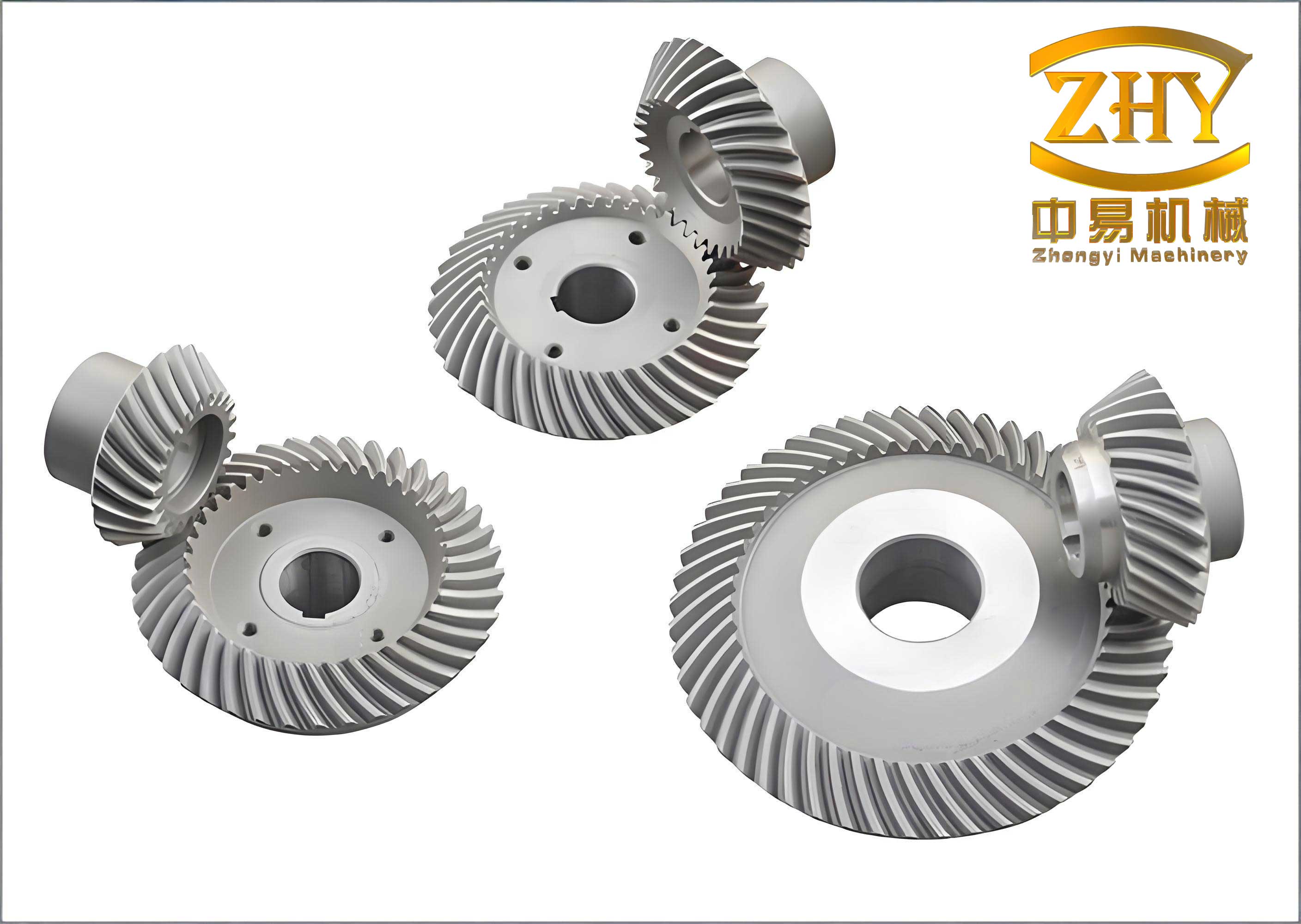
The image above provides a visual reference for hyperbolic gears, showcasing their intricate tooth geometry. In my simulations, I aim to replicate such details accurately. To facilitate this, I often summarize the simulation steps in a table, which helps in organizing the process and ensuring consistency. Below is a table outlining the key stages in virtual manufacturing for hyperbolic gears:
| Stage | Description | Tools/Software Used |
|---|---|---|
| 1. Gear Blank Modeling | Create a 3D model of the raw gear blank based on design parameters. | UG NX, CATIA |
| 2. Tool Modeling | Define the cutter geometry (e.g., blade profile, radius) as per machining requirements. | VERICUT, CAD software |
| 3. Machine Kinematics Setup | Configure the virtual machine with axes movements, rotations, and offsets. | VERICUT |
| 4. NC Code Generation | Generate or import G-code that controls the tool path based on cutting theory. | Post-processors, CAM software |
| 5. Simulation Execution | Run the simulation to perform material removal and generate the gear teeth. | VERICUT |
| 6. Result Analysis | Inspect the digital gear for errors, surface quality, and compliance with design. | Measurement tools in software |
Through this virtual approach, I have been able to experiment with different machine settings for hyperbolic gears, such as changing the cutter tilt or adjusting the feed rates, to see their impact on tooth contact patterns. This is crucial for optimizing performance in automotive differentials, where noise and durability are paramount. Furthermore, the simulation data can be used to compensate for machining errors by tweaking the NC code, thereby enhancing the accuracy of hyperbolic gears.
In addition to simulation, I have also explored reverse engineering techniques for hyperbolic gears. This involves measuring a physical gear using coordinate measuring machines (CMM) to obtain point cloud data of the tooth surfaces. The data is then processed to create a digital model that reflects the as-manufactured geometry. In my work, I have used this method to compare theoretical models with real parts, identifying deviations and refining the modeling algorithms. The reverse engineering process can be summarized by the following steps: data acquisition, point cloud processing, surface reconstruction, and model validation. The mathematical basis for surface fitting often involves non-uniform rational B-splines (NURBS), which provide flexibility in representing complex curves. The NURBS surface equation is:
$$\mathbf{S}(u,v) = \frac{\sum_{i=0}^n \sum_{j=0}^m N_{i,p}(u) N_{j,q}(v) w_{i,j} \mathbf{P}_{i,j}}{\sum_{i=0}^n \sum_{j=0}^m N_{i,p}(u) N_{j,q}(v) w_{i,j}}$$
where $$\mathbf{P}_{i,j}$$ are control points, $$w_{i,j}$$ are weights, and $$N_{i,p}$$ are basis functions of degree $$p$$. By applying this to the measured points from hyperbolic gears, I can reconstruct a high-accuracy digital twin that accounts for manufacturing imperfections. This model is invaluable for tasks like wear analysis or redesign, especially when dealing with legacy hyperbolic gears where original design parameters are lost.
Now, let’s compare the different modeling methods for hyperbolic gears. Each method has its strengths and weaknesses, and in practice, I often combine them to leverage their advantages. For instance, I might use design-based modeling for initial concept development, cutting theory for precise tooth form generation, and virtual simulation for verification. The table below provides a comparative analysis:
| Method | Basis | Advantages | Disadvantages | Suitability |
|---|---|---|---|---|
| Design Parameter Modeling | Direct use of gear design parameters in CAD | Fast, easy to modify, good for preliminary design | May lack accuracy for complex tooth surfaces | Concept design and parameter studies |
| Cutting Theory Modeling | Mathematical derivation from cutting tool path | High accuracy, reflects actual manufacturing process | Computationally heavy, requires deep mathematical knowledge | Precision engineering and research |
| Virtual Manufacturing Simulation | Simulation of machining via Boolean operations | Validates tool paths, detects errors, cost-effective | Depends on accurate machine and tool models | NC programming and process optimization |
| Reverse Engineering | Measurement of physical gears | Captures as-built geometry, useful for analysis | Time-consuming, requires measurement equipment | Quality control and legacy part replication |
From this comparison, it’s evident that hyperbolic gears demand a multifaceted modeling approach. In my research, I have integrated these methods to develop a comprehensive digital workflow. For example, I start with design parameters to create a gear blank, then use cutting theory equations to generate tool paths, simulate the milling in VERICUT, and finally, validate the model with CMM data if available. This integrated approach ensures that the digital models of hyperbolic gears are both theoretically sound and practically viable.
To delve deeper into the cutting theory, let’s consider the kinematics of a five-axis CNC machine used for hyperbolic gear milling. The machine typically has three linear axes (X, Y, Z) and two rotational axes (A, C) to achieve the complex motions required for hyperbolic gears. The transformation from the tool coordinate system to the workpiece system involves a series of homogeneous transformations. Denoting the machine axes positions as $$[X, Y, Z, A, C]$$, the overall transformation matrix $$\mathbf{M}$$ can be expressed as:
$$\mathbf{M} = \mathbf{T}_Z(Z) \cdot \mathbf{T}_Y(Y) \cdot \mathbf{T}_X(X) \cdot \mathbf{R}_A(A) \cdot \mathbf{R}_C(C)$$
where $$\mathbf{T}$$ and $$\mathbf{R}$$ represent translation and rotation matrices, respectively. For hyperbolic gears, the values of these axes are computed based on the cradle-style machine settings, which include parameters like machine root angle, sliding base setting, and eccentric angle. The relationship between these settings and the CNC axes can be derived using geometric relationships. For instance, the rotational angle $$C$$ often corresponds to the work rotation $$\phi$$, while $$A$$ relates to the cutter tilt. By solving these equations, I can generate NC code that drives the virtual simulation, thereby creating accurate models of hyperbolic gears.
Another important formula in the context of hyperbolic gears is the tooth contact analysis (TCA) equation, which predicts the contact pattern under load. TCA is essential for ensuring smooth operation and longevity. The basic principle involves finding points on the pinion and gear tooth surfaces where the surfaces are in contact, i.e., where their normals align and the surfaces are tangent. Mathematically, this is expressed as:
$$\mathbf{n}_p \times \mathbf{n}_g = \mathbf{0}$$
$$\mathbf{r}_p – \mathbf{r}_g = \mathbf{d}$$
where $$\mathbf{n}_p$$ and $$\mathbf{n}_g$$ are the unit normals at contact points on the pinion and gear, $$\mathbf{r}_p$$ and $$\mathbf{r}_g$$ are position vectors, and $$\mathbf{d}$$ is the relative displacement vector. Solving these equations for hyperbolic gears requires iterative numerical methods due to the surfaces’ complexity. In my modeling, I use TCA to optimize tooth modifications, such as crowning or bias, which improve the contact pattern and reduce noise. This is particularly critical for automotive differentials, where hyperbolic gears must operate reliably under varying loads.
In terms of software implementation, I have developed scripts and macros to automate parts of the modeling process. For example, in UG NX, I use expressions to link design parameters so that changes propagate automatically through the model. This parametric modeling approach saves time and reduces errors. Similarly, in MATLAB, I have functions that compute tooth surface points for hyperbolic gears based on input parameters like offset $$E$$ and spiral angle $$\beta$$. These tools enable rapid exploration of design alternatives, fostering innovation in hyperbolic gear applications.
Looking ahead, the modeling of hyperbolic gears is evolving with advancements in digital twin technology and artificial intelligence. By incorporating real-time data from manufacturing sensors, we can create dynamic models that adapt to production variations. Additionally, machine learning algorithms can predict optimal machining parameters for hyperbolic gears based on historical data, further enhancing efficiency. In my ongoing work, I am investigating these trends to push the boundaries of hyperbolic gear modeling.
In conclusion, hyperbolic gears are indispensable in automotive differentials and other mechanical systems, and their accurate modeling is key to unlocking their full potential. Through a combination of design-based, theory-driven, and simulation-assisted methods, we can create high-fidelity digital models that support optimization, virtual testing, and error compensation. The tables and formulas presented here summarize the core concepts, and the repeated emphasis on hyperbolic gears underscores their significance. As technology progresses, I believe that integrated digital workflows will become standard for hyperbolic gears, leading to more reliable and efficient transmissions. My research continues to contribute to this field, and I encourage further exploration into the sophisticated world of hyperbolic gears.