
In the finite element method, the continuum structure is considered to be composed of finite elements connected by finite nodes. Each element represents the corresponding local structure of mechanical parts. If the mechanical properties of each element are close to those of the corresponding local structure in the mechanical parts, the more accurate the simulation results will be. In order to make the simulation results more ideal, the mesh element used in the finite element model should reflect the mechanical characteristics of the mechanical parts in the actual production as much as possible. It is not only required that every structural element be consistent with the corresponding actual mechanical part geometry, but also required that the transfer force and transfer motion of the element be consistent with the actual situation.
The reliability of the finite element simulation results is directly affected by the mechanical characteristics of the simulation model and the actual engineering structure. The gear transmission mechanism is a very complex composite structure. The first condition to ensure the accuracy of the simulation results is to simplify the finite element model properly on the basis of the actual structure. Therefore, it is necessary to simplify the established finite element simulation model of gear components, so that the simulation model can reflect the actual engineering problems with small errors. Therefore, the accuracy of the finite element simulation results mainly depends on the accuracy of the simulation model.
One of the most important steps in building the finite element simulation model is to mesh the three-dimensional model. The mesh form directly affects the calculation accuracy of the simulation model. Because the finite element simulation is to discretize the model into many small elements, which are connected by nodes, and then impose constraints and loads on the nodes, therefore, the specific position of adding constraints and loads should be considered before meshing, and then the finite element simulation model should be processed accordingly.
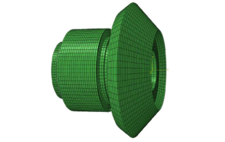
The finite element mesh model of gear components is established by HyperMesh software, the structure of gear components is properly simplified and the mesh of gear shaft shoulder is finely divided, and the regular regular hexahedral solid element mesh model as shown in Figure 2.6 is obtained, with the total number of elements of 50672.
Since the gear shaft and bearing belong to two different metal materials, it is necessary to define their material properties separately.