
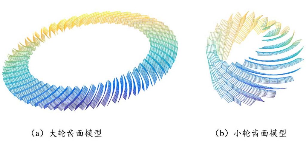
The modeling method of FH hypoid gear is shown in Fig. 1
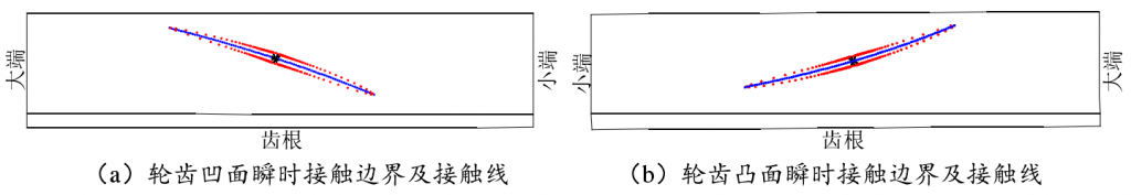
The two tooth surfaces are assembled in the assembly coordinate system, and the tooth contact analysis is carried out with the above method
The results are shown in Figure 2, and the results of TCA are consistent with those in the literature. The contact ellipse boundary and instantaneous contact line (i.e. the major axis of contact ellipse distinguished in the previous paper) are shown in the figure.
In order to compare the difference between this method and the previous method, the contact ellipse and contact line obtained by the previous method are drawn in this result, and the two results are locally enlarged at the meshing center, as shown in Fig. 3. The black solid line in the figure represents the standard ellipse in the previous method, the green dotted line represents the contact line in the previous method, that is, the long axis, while the red dot and blue five pointed star represent the instantaneous contact ellipse boundary and contact line in this method.
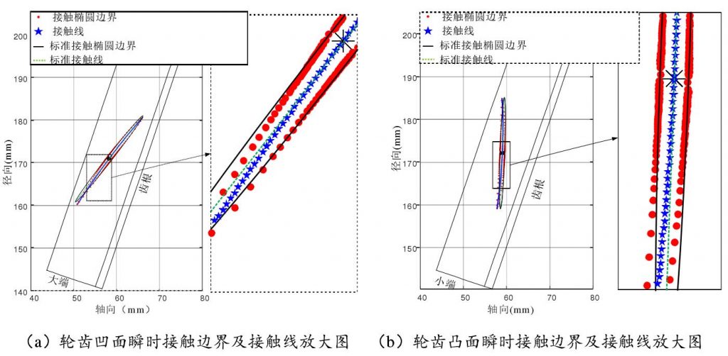
As can be seen from the figure, the contact ellipse is not a standard ellipse, and the contact line is not a straight line. This is because point P is not the symmetry center of two meshing tooth surfaces for complex curved surface gears such as hypoid gears. When elastic deformation occurs in the meshing of two tooth surfaces, the contact near point P will be different. Therefore, the “long axis” and “short axis” of “contact ellipse” will not be straight lines, and their boundaries will not be standard ellipses. The above results well illustrate this point, so this method can get more accurate contact ellipse boundary and contact line, and lay a foundation for further load-bearing contact analysis (LTCA).
The instantaneous contact ellipse boundary and contact line at each contact point from entering to exiting meshing are projected onto the rotating projection surface to form the whole contact mark, as shown in Fig. 4 (the contact mark in the figure takes into account the contact of the tooth edge, and the line composed of black stars in the middle is the contact trace)
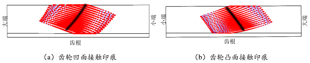
This method of tooth contact analysis based on numerical iteration not only avoids the derivation of complex principal curvature and principal direction of paired tooth surface in traditional tooth contact simulation, but also reflects the actual contact situation of tooth surface. It should be noted that the instantaneous “contact ellipse” is not a standard ellipse, and the instantaneous contact line is not a straight line. This conclusion is only applicable to the case of hypoid gear and other complex curved surface gear, and the two contact tooth surfaces are asymmetric about the contact point.