
TE at small wheel φ1A is smaller than LTE under larger load, indicating that the gap between teeth is not enough to compensate for the effect of tooth-to-tooth on load deformation of 1. Rolling interference will occur on the modified tooth surface. When the tooth-to-tooth engages, the actual meshing point will start at the tip of the large gear.Under this condition, the solution of the position of the rodent point is relatively complex, and it is necessary to solve the actual rodent point of the standard tooth surface at a higher load first.
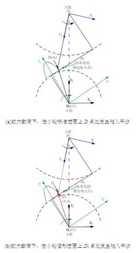
In Figure 5(a), under high load, the rodent interference occurs at point D on the standard tooth surface of the small wheel, and point A0 is the tip point of the large wheel.At this point, for the modified teeth, there is still a certain gap between the small teeth and the large teeth apex due to the modification of the small teeth in the direction of the teeth and the root in the rodent area, so there is no rodent interference at this point.However, the amount of modification in the rodent area is not enough to compensate for the load deformation of the previous pair of teeth, and the rodent interference will always occur as the large and small gears continue to rotate.
In Fig. 5(b), assuming the angular position of the standard tooth surface in which the interference occurs and the continuing rotation angle of the large and small wheels is_, the interference will occur at point D1 on the modified tooth surface of the small wheels.At this point, if the geometrical space position of the large and small wheels is taken into account, the tip point of the large gear will be embedded in the standard tooth face of the small gear.The insertion amount of large gear tip point A0 in the standard tooth of small gear is called interference quantity in this paper. It can be obtained by solving the shortest distance A0 to the standard involute in the plane of XfOfYf under the fixed coordinate system Sf.
When the shortest distance from the solution point to the standard involute is obtained, two equations can be obtained by means of geometric properties.The points on the involute need to satisfy the involute equation, so the first equation can be obtained:
F (x, y) = 0 (1)
Set point D2 is a point on the standard involute. In fixed coordinate system, the distance between point A0f (x0f, y0f) and point D2f (xD2f, yD2f) is the minimum distance from the tip point of large gear teeth to the standard involute.Thus a second equation can be obtained:
T_D2f.W_D2f=0 (2)
In formula: T_D2f (fy, fx) is tangent vector of standard involute at D2f point; W_D2f (xD2f_x0f, yD2f_y0f) is position vector.
When the tip of large gear teeth contacts with the modified tooth surface of small gear, the third equation can be obtained according to the equal interference and modification:
Delta=(xD2f_x0f)2+(yD2f_y0f)2(3)
Where delta is the modification quantity, (xD2f_x0f) 2+ (yD2f_y0f) 2 is the interference quantity.
The simultaneous equation (1) ~ (3) can be used to obtain the coordinates of the small Δω and D2 points (xD21, yD21) of the rotation of large and small wheels when the meshing interference occurs on the modified tooth surface.
From the above analysis, it can be seen that when the rodent interference occurs on the modified tooth surface, the angle at which the large wheel deviates from the theoretical rodent position is subtracted_from the angle at which the rodent interference occurs under the standard tooth surface condition.After obtaining the deviation angle of the large wheel at the theoretical rodent position, the angle can be superimposed on the angle of the large wheel theoretical rodent position. The position vector of the rodent impact point can be obtained by the contact analysis between the small gear tooth surface and the large wheel at the new position.