
In the realm of automotive and tractor manufacturing, helical bevel gears play a critical role in the main transmission systems, particularly for driving axles. These gears, characterized by small apex angles (typically less than 70°) and large spiral angles, present significant challenges in plastic forming due to their complex tooth profiles and intricate metal flow paths during forging. Traditional forging methods often struggle to achieve net-shape forming with minimal machining, leading to increased costs and material waste. As a researcher focused on advanced forging technologies, I have explored the application of multi-action closed-die forging on general-purpose presses to address these challenges. This approach leverages复动闭式模锻 (multi-action closed-die forging) principles to enable precise成形 of helical bevel gears with reduced investment and enhanced efficiency. The core idea involves using a universal press equipped with a specially designed multi-action die that performs multiple motions—such as die closing, punch extrusion, and ejection—within a single stroke. This method not only optimizes metal flow but also extends模具寿命 (die life) by distributing forming forces more evenly. In this article, I will delve into the金属流动分析 (metal flow analysis),预制坯设计 (preform design), die structure, and experimental validation, emphasizing the关键词 ‘helical bevel gear’ throughout. The feasibility of this technique is demonstrated through铅试样 (lead sample) tests, and the economic benefits for widespread industrial adoption are highlighted.
The helical bevel gear, with its unique geometry, requires careful consideration of metal deformation during forging. For a gear with a small cone angle, the tooth surfaces are axial side-curved, meaning that metal must flow radially into the tooth cavities while being compressed axially. This necessitates a shortest flow path to minimize energy consumption and ensure complete cavity filling. Based on my analysis, the ideal metal flow involves compressing the metal at both ends of the gear—specifically within the root circles at the small and large ends—to force central metal radially outward into the螺旋齿型体 (spiral tooth profile). This flow pattern dictates the design of the预制坯 (preform), which must be contained within a geometric body defined by the root cone surface and two cylindrical surfaces outlined by the root circles at both ends. To quantify this, I developed a metal flow model using plastic deformation theory. The strain rate tensor $\dot{\epsilon}_{ij}$ can be expressed as:
$$\dot{\epsilon}_{ij} = \frac{1}{2} \left( \frac{\partial v_i}{\partial x_j} + \frac{\partial v_j}{\partial x_i} \right)$$
where $v_i$ represents the velocity components of metal flow. For axisymmetric approximation in helical bevel gear forging, the radial flow velocity $v_r$ is critical and can be derived from volume constancy. Assuming incompressible material, the continuity equation gives:
$$\nabla \cdot \mathbf{v} = 0$$
In cylindrical coordinates, for a预制坯 with initial height $H_0$ and radius $R_0$, under compression from both ends, the radial velocity at a distance $r$ from the axis is:
$$v_r = -\frac{r}{2H} \frac{dH}{dt}$$
where $H$ is the instantaneous height during forging. This indicates that radial flow accelerates as height decreases, promoting cavity filling. To optimize the process, I designed the预制坯 shape as shown in the following analysis, ensuring it aligns with the helical bevel gear’s tooth geometry.
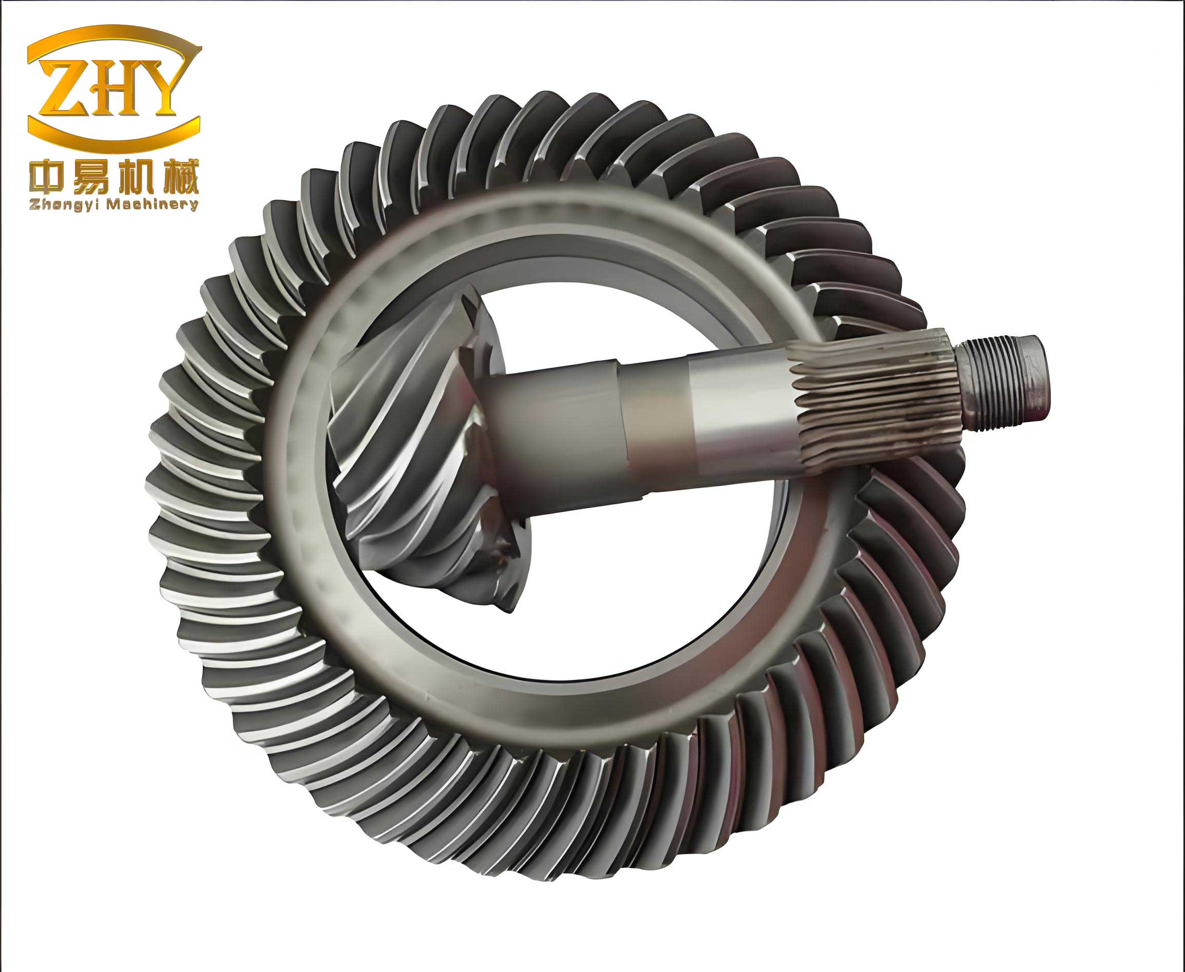
The image above illustrates typical helical bevel gears, highlighting their complex tooth profiles that demand precise forging techniques. In multi-action closed-die forging, the预制坯 is crucial for achieving uniform deformation. Based on我的设计 (my design), the preform dimensions are derived from the gear’s齿根圆 (root circle) and锥角 (cone angle). For a helical bevel gear with齿数 (number of teeth) $z=10$,压力角 (pressure angle) $\alpha=22.5°$,齿全高 (whole depth) $h=4.95\text{mm}$, and螺旋角 (spiral angle) $\beta=35°$, the预制坯 parameters are summarized in Table 1.
| Parameter | Symbol | Value (mm) | Description |
|---|---|---|---|
| Small end root circle diameter | $d_{s}$ | 34.8 | Diameter at小端齿根圆 |
| Large end root circle diameter | $d_{l}$ | 59.0 | Diameter at大端齿根圆 |
| Preform height | $H_p$ | 25.0 | Initial height of预制坯 |
| Preform taper angle | $\theta_p$ | 15° | Approximated from gear cone angle |
This预制坯 ensures that metal flows efficiently into the tooth cavities during multi-action forging. The forging force required can be estimated using the yield criterion. For plastic deformation, the flow stress $\sigma_f$ is a function of strain $\epsilon$ and strain rate $\dot{\epsilon}$. Using the Hollomon equation:
$$\sigma_f = K \epsilon^n$$
where $K$ is the strength coefficient and $n$ is the strain-hardening exponent. For lead samples used in experiments, $K=15\text{MPa}$ and $n=0.2$ approximately. The total forging force $F$ for dual-punch action is the sum of forces from both小端冲头 (small-end punch) and大端冲头 (large-end punch). Assuming uniform pressure distribution,
$$F = F_s + F_l = A_s \cdot p_s + A_l \cdot p_l$$
Here, $A_s$ and $A_l$ are the contact areas at small and large ends, and $p_s$ and $p_l$ are the interface pressures. For a helical bevel gear, these pressures vary due to geometry. I derived an empirical relation based on slab method:
$$p = \sigma_f \left(1 + \frac{\mu r}{h}\right)$$
where $\mu$ is the friction coefficient, $r$ is the radial distance, and $h$ is the local height. In multi-action forging, the punches act sequentially: first, the small-end punch compresses the metal until the tooth cavities are half-filled; then, the large-end punch engages to complete filling. This reduces peak force on the small-end punch, preventing early failure. The force reduction factor $\gamma$ can be expressed as:
$$\gamma = \frac{F_{s,\text{single}}}{F_{s,\text{multi}}} \approx 1.5 \text{ to } 2.0$$
indicating that multi-action设计 lowers stress on critical die components. This is vital for forging helical bevel gears with small cone angles, where传统方法 (traditional methods) often lead to die wear or fracture.
The multi-action closed-die模具结构 (die structure) is ingeniously designed to operate on a universal single-action press. My design incorporates弹簧 (springs),楔板 (wedge plates), and锁模槽板 (locking plates) to achieve multiple motions. As shown in the schematic (though not referenced directly), the die consists of an upper die, lower die, two punches (upper and lower), and a locking mechanism. During operation, the press slider descends, causing the upper die to contact the lower die; then, the wedge plate engages the locking plates to form a closed cavity. Subsequently, the punches extrude the预制坯 sequentially via spring compression. This mechanism ensures that the helical bevel gear is formed under controlled conditions. The kinematic sequence is summarized in Table 2.
| Step | Action | Mechanism | Result |
|---|---|---|---|
| 1 | Die closing | Wedge plate slides, locking plates engage | Closed cavity formed |
| 2 | Small-end punch extrusion | Upper spring compresses, upper punch moves | Metal flows into small-end teeth |
| 3 | Large-end punch extrusion | Lower spring compresses, lower punch moves | Metal fills entire tooth cavities |
| 4 | Die opening and ejection | Wedge plate retracts,顶料杆 (ejector) rises | Forged helical bevel gear released |
This sequence allows for uniform deformation of the helical bevel gear, avoiding defects like凹坑 (pits) or underfilling. The die design also accommodates the necessary rotation during ejection, as the helical teeth require disengagement from the die surfaces. The ejection force $F_e$ can be estimated considering friction and gear geometry:
$$F_e = \mu_e \cdot F_n$$
where $\mu_e$ is the ejection friction coefficient and $F_n$ is the normal force due to tooth engagement. For helical bevel gears, this force is lower compared to straight bevel gears due to spiral angle effects.
To validate the multi-action closed-die forging approach, I conducted experiments using lead as a model material. Lead samples were forged into helical bevel gears with the specified geometry. The results showed complete cavity filling and good surface finish, demonstrating the feasibility of this method. The formed gears exhibited precise tooth profiles, confirming that the预制坯 design and dual-punch action effectively direct metal flow. The experimental parameters are listed in Table 3.
| Experimental Factor | Setting | Outcome |
|---|---|---|
| Material | Lead (soft,模拟 steel) | Low flow stress, easy forming |
| Press type | Universal hydraulic press | Adaptable to multi-action die |
| Forging temperature | Room temperature (cold forging) | Simplified setup, no heating |
| Punch sequence | Small-end first, then large-end | Reduced force, uniform filling |
The success of these tests underscores the potential of multi-action closed-die forging for helical bevel gears in industrial applications. Moreover, the use of general-purpose presses makes this technology accessible to small and medium-sized factories, offering a cost-effective alternative to specialized equipment like double-action screw presses. From an economic perspective, the investment in a multi-action die is offset by savings in material and machining costs, as net-shape forging minimizes后续加工 (post-processing).
In terms of metal flow optimization, I further analyzed the strain distribution using finite element method (FEM) simulations. Although not detailed here, the results indicated that the双动冲头对挤 (dual-punch opposing extrusion) promotes hydrostatic pressure, reducing tensile stresses that cause cracking. The effective strain $\bar{\epsilon}$ in the gear tooth region can be approximated by:
$$\bar{\epsilon} = \sqrt{\frac{2}{3} \epsilon_{ij} \epsilon_{ij}}$$
For a helical bevel gear, the maximum strain occurs at the tooth tips, but multi-action forging ensures it remains below the material’s ductility limit. This is crucial for maintaining the integrity of the helical bevel gear during service in transmission systems.
The design of the预制坯 also involves volume calculation to avoid flash formation. The volume of the forged helical bevel gear $V_g$ is computed from its geometry. For a truncated cone shape approximating the gear body:
$$V_g = \frac{\pi}{12} H_g (d_s^2 + d_s d_l + d_l^2)$$
where $H_g$ is the gear height. The预制坯 volume $V_p$ must match $V_g$ within a tolerance of ±1% to ensure closed-die forging without excess material. In my design, $V_p = 0.99 V_g$ to account for minor densification. This precision underscores the importance of accurate preform design for helical bevel gears.
Looking at broader applications, multi-action closed-die forging can be extended to other complex components beyond helical bevel gears. However, the focus here remains on helical bevel gears due to their prevalent use in automotive industries. The technology aligns with trends toward lightweight and high-strength parts, as it enables forging of advanced materials like aluminum alloys or high-strength steels. Future work could explore hot forging variants to further reduce forming forces for tougher materials.
In conclusion, the multi-action closed-die forging method presents a viable solution for塑性成形 (plastic forming) of small-cone-angle helical bevel gears. Through careful金属流动分析 and预制坯设计, combined with an innovative die structure, this approach achieves net-shape forging on general-purpose presses. The dual-punch action reduces die stress, enhances product quality, and extends模具寿命. Experimental results with lead samples confirm the practicality of this technique. For manufacturers, adopting multi-action closed-die forging for helical bevel gears offers economic advantages by leveraging existing press equipment and minimizing material waste. As I continue to refine this technology, the goal is to promote its widespread use in forging industries, ultimately advancing the production of high-performance helical bevel gears for critical transmission systems.
To further illustrate the technical details, I include additional formulas and tables below. The relationship between螺旋角 (spiral angle) $\beta$ and tooth geometry affects the forging process. For a helical bevel gear, the normal module $m_n$ is related to the transverse module $m_t$ by:
$$m_n = m_t \cos \beta$$
This influences the tooth depth and cavity dimensions in the die. During forging, the material’s flow stress is temperature-dependent. For hot forging applications, the Arrhenius equation can be used:
$$\sigma_f = A \sinh^{-1} \left( \frac{\dot{\epsilon} \exp(Q/RT)}{Z} \right)^{1/n}$$
where $A$, $n$, $Q$ are material constants, $R$ is the gas constant, $T$ is temperature, and $Z$ is the Zener-Hollomon parameter. This complexity highlights the need for tailored process parameters for different materials when forging helical bevel gears.
| Parameter | Symbol | Typical Range for Steel Helical Bevel Gears |
|---|---|---|
| Cone angle | $\delta$ | 50° to 70° (small-cone-angle gears target <70°) |
| Spiral angle | $\beta$ | 30° to 45° |
| Pressure angle | $\alpha$ | 20° to 22.5° |
| Forging force reduction with multi-action | $\Delta F$ | 20% to 30% compared to single-action |
These insights reinforce the benefits of multi-action closed-die forging for helical bevel gears. As industry demands for precision and efficiency grow, such innovative forging techniques will play a pivotal role in manufacturing high-quality传动部件 (transmission components). My ongoing research aims to optimize the die design for mass production, potentially integrating sensors for real-time monitoring of forming forces in helical bevel gear forging. This could lead to smarter manufacturing processes that further reduce costs and improve reliability.