
In modern aero-engine design, the transmission system’s reliability and stability are paramount, especially when employing elastic supports to mitigate vibration. The spiral bevel gear, a critical component in such systems, exhibits altered contact patterns and transmission errors under elastic support conditions due to shaft center whirl trajectories. This study focuses on developing a multi-objective optimization framework for the machine-tool settings of spiral bevel gears to ensure optimal contact characteristics in elastic support environments. By transforming elastic deformations into equivalent misalignments and establishing a comprehensive tooth contact analysis model, I aim to pre-control the bearing contact and transmission error before gear design. The optimization targets the minimization of deviations in contact pattern center points and transmission error magnitudes from their rigid support counterparts, using a weighted sum approach with coordinate rotation search. Through detailed mathematical formulations, including extensive use of equations and tables, this paper provides a methodology to enhance the meshing quality of spiral bevel gears in elastic support systems, validated via a case study from an aero-engine rotor system.
The integration of elastic supports in aero-engines improves vibration characteristics but introduces complexities in gear contact behavior. For spiral bevel gears, the shaft’s elastic deformation leads to time-varying misalignments, affecting the contact patch and transmission error, which can compromise performance and durability. Traditional design methods often assume rigid supports, overlooking these dynamic effects. Therefore, a proactive design strategy is essential. This study addresses this gap by optimizing the cutting parameters of spiral bevel gears to achieve desired contact properties under elastic support. The approach involves modeling the rotor system’s elastic deformations, converting them into installation errors, and incorporating them into gear contact equations. A multi-objective optimization is then performed on the pinion’s machine-tool settings, ensuring that the spiral bevel gear operates with minimal contact deviations and symmetric transmission error curves across operational speeds.
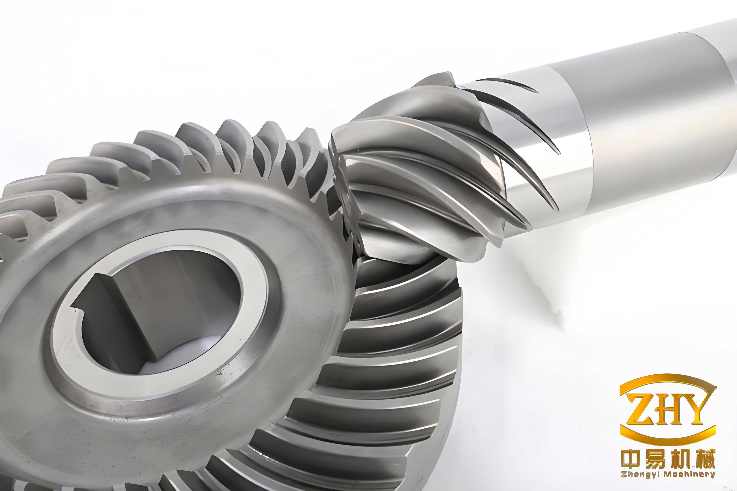
Elastic supports in aero-engine rotors cause displacements at the gear mounting locations, which can be equivalently treated as installation errors in spiral bevel gear pairs. Consider a coordinate system $\Sigma = (0, x, y, z)$ with its origin at the intersection point of the gear axes. The $x$-axis and $y$-axis align with the pinion and gear axes, respectively, pointing toward the gear’s large end, while the $z$-axis is perpendicular to the plane containing both axes. The deformations at the pinion cone apex, resulting from rotor imbalance and load-induced deflections, are expressed as:
$$
\Delta x = \delta_x, \quad \Delta y = \delta_y + f \cos(\omega t), \quad \Delta z = \delta_z + f \sin(\omega t), \quad \Delta \varepsilon = \delta_\sigma + \theta.
$$
Here, $\Delta x$, $\Delta y$, $\Delta z$, and $\Delta \varepsilon$ represent linear and angular deformations; $\delta_x$, $\delta_y$, $\delta_z$, and $\delta_\sigma$ are deformations due to meshing forces; $f$ and $\theta$ are the displacement and angular deflection from rotor unbalance, respectively, with $\omega$ as the angular speed. The whirl trajectory forms an ellipse, described by:
$$
f = \frac{f_y f_z}{\sqrt{f_y^2 \sin^2(\omega t) + f_z^2 \cos^2(\omega t)}}, \quad \theta = \frac{\theta_y \theta_z}{\sqrt{\theta_y^2 \sin^2(\omega t) + \theta_z^2 \cos^2(\omega t)}}.
$$
where $f_y$, $f_z$ and $\theta_y$, $\theta_z$ are the linear and angular displacements along the $y$ and $z$ directions. To account for the maximum impact, the peak values are used to define installation errors analogous to H-V testing adjustments:
$$
\Delta H = \max(\Delta y), \quad \Delta J = \max(\Delta x), \quad \Delta V = \max(\Delta z), \quad \Delta \delta = \max(\Delta \varepsilon).
$$
These errors, $\Delta H$, $\Delta J$, $\Delta V$, and $\Delta \delta$, correspond to offsets in the axial, horizontal, vertical, and shaft angle directions, respectively. For the spiral bevel gear pair, the gear is assumed rigidly supported due to its stiffer mounting, so only pinion deformations are considered. This transformation simplifies the dynamic problem into a static misalignment analysis, enabling the use of established gear contact models.
To analyze the contact of spiral bevel gears under elastic support, a tooth contact analysis (TCA) model is developed. The gear tooth surfaces are generated via face-milling processes, and their equations are derived in respective coordinate systems. For the gear (driven member), the cutter surface $\vec{r}_{eg}$ and normal $\vec{n}_{eg}$ are transformed to the gear fixed coordinate system $\Sigma_{02}$ using homogeneous transformation matrices:
$$
\vec{r}_{02}^{(2)} = [M_{4g}][M_{3g}][M_{2g}][M_{1g}] \vec{r}_{eg}, \quad \vec{n}_{02}^{(2)} = [M_{4g}][M_{3g}][M_{2g}][M_{1g}] \vec{n}_{eg}.
$$
The matrices $[M_{1g}]$, $[M_{2g}]$, $[M_{3g}]$, and $[M_{4g}]$ represent coordinate transformations from the cutter to the gear. The meshing condition during gear generation is:
$$
\vec{v}_{e,2}^{m2} \cdot \vec{n}_{m2}^{(e2)} = 0,
$$
where $\vec{v}_{e,2}^{m2}$ is the relative velocity between the cutter and gear, and $\vec{n}_{m2}^{(e2)}$ is the cutter surface normal in the machine coordinate system $\Sigma_{m2}$. Combining these equations yields the gear tooth surface $\vec{r}_{02}^{(2)}(\theta_g, \phi_g)$, with $\theta_g$ and $\phi_g$ as parameters.
Similarly, for the pinion (driving member), the cutter surface $\vec{r}_{ep}$ and normal $\vec{n}_{ep}$ are transformed to the pinion fixed coordinate system $\Sigma_{01}$:
$$
\vec{r}_{01}^{(1)} = [M_{4p}][M_{3p}][M_{2p}][M_{1p}] \vec{r}_{ep}, \quad \vec{n}_{01}^{(1)} = [M_{4p}][M_{3p}][M_{2p}][M_{1p}] \vec{n}_{ep}.
$$
With matrices $[M_{1p}]$, $[M_{2p}]$, $[M_{3p}]$, and $[M_{4p}]$ for pinion generation. The meshing equation is:
$$
\vec{v}_{e,1}^{m1} \cdot \vec{n}_{m1}^{(e1)} = 0,
$$
giving the pinion tooth surface $\vec{r}_{01}^{(1)}(\theta_p, \phi_p)$. To perform TCA under elastic support, the installation errors $\Delta H$, $\Delta J$, $\Delta V$, and $\Delta \delta$ are incorporated. The pinion surface is transformed to the gear fixed coordinate system $\Sigma_{02}$ using a misalignment matrix $[M_{12}]$:
$$
[M_{12}] = \begin{bmatrix}
\sin \Delta \delta & \cos \Delta \delta & 0 & p – \Delta H \\
-\cos \Delta \delta & \sin \Delta \delta & 0 & \Delta J \\
0 & 0 & 1 & -\Delta V \\
0 & 0 & 0 & 1
\end{bmatrix},
$$
where $p$ is the distance between gear cone apexes. Thus:
$$
\vec{r}_{02}^{(1)} = [M_{12}] \vec{r}_{01}^{(1)}, \quad \vec{n}_{02}^{(1)} = [M_{12}] \vec{n}_{01}^{(1)}.
$$
The contact conditions require position and normal vector continuity at the meshing point:
$$
\vec{r}_{02}^{(1)} = \vec{r}_{02}^{(2)}, \quad \vec{n}_{02}^{(1)} = \vec{n}_{02}^{(2)}.
$$
Additionally, the relative velocity between the pinion and gear must be orthogonal to the common normal:
$$
\vec{v}_{02}^{(1,2)} \cdot \vec{n}_{02}^{(2)} = 0,
$$
where $\vec{v}_{02}^{(1,2)}$ is the relative velocity vector in $\Sigma_{02}$, expressed as:
$$
\vec{v}_{02}^{(1,2)} = \begin{bmatrix}
\omega^{(2)} i_m [(y_{02}^{(2)} – \Delta J) \cos \Delta \delta – (z_{02}^{(2)} + \Delta V) \cos \Delta \delta] – z_{02}^{(2)} \\
i_m \cos \Delta \delta (z_{02}^{(2)} + \Delta V) \\
i_m [(x_{02}^{(2)} – p + \Delta H) \sin \Delta \delta – (y_{02}^{(2)} – \Delta J) \cos \Delta \delta] + x_{02}^{(2)}
\end{bmatrix},
$$
with $i_m = z_2 / z_1$ as the gear ratio, and $z_1$, $z_2$ as the tooth numbers of pinion and gear. Solving these equations numerically yields the contact path and transmission error. The transmission error $\delta \phi_{21}$ is defined as:
$$
\delta \phi_{21} = (\phi_2 – \phi_2^0) – (\phi_1 – \phi_1^0) \cdot z_1 / z_2,
$$
where $\phi_1^0$ and $\phi_2^0$ are initial rotation angles. Under elastic support, the contact pattern center point $P_t(p_{tx}, p_{ty})$ and transmission error magnitude $|\delta \phi_{2t}|$ deviate from those under rigid support, $P_0(p_{0x}, p_{0y})$ and $|\delta \phi_{20}|$. The goal is to minimize these deviations through optimization of the pinion’s machine-tool settings.
The multi-objective optimization aims to adjust the pinion cutting parameters so that the spiral bevel gear’s contact characteristics under elastic support approximate the ideal rigid support case. The objectives are to minimize the absolute differences in contact center coordinates and transmission error magnitudes. Let $a_t$ and $a_0$ represent the contact path inclination angles under elastic and rigid supports, respectively. The optimization problem is formulated as:
$$
\min |p_{tx} – p_{0x}|, \quad \min |p_{ty} – p_{0y}|, \quad \min |a_t – a_0|, \quad \min |\delta \phi_{2t} – \delta \phi_{20}|.
$$
For spiral bevel gears manufactured via grinding, key optimization variables are the pinion cutter pressure angle $\alpha_1$, the first derivative of the roll ratio $m’_{P1}$, and a micro-adjustment $\delta y$ for the reference point position along the tooth height. Using a linear weighted sum method, a composite objective function is constructed:
$$
\min f(\alpha_1, m’_{P1}, \delta y) = w_1 |p_{tx} – p_{0x}| + w_2 |p_{ty} – p_{0y}| + w_3 |a_t – a_0| + w_4 |\delta \phi_{2t} – \delta \phi_{20}|,
$$
with weight coefficients satisfying $w_1 + w_2 + w_3 + w_4 = 1$. Based on sensitivity analysis, the contact pattern location is most critical, followed by inclination angle and transmission error. Thus, weights are set as $w_1 = 0.35$, $w_2 = 0.35$, $w_3 = 0.2$, and $w_4 = 0.1$. The variables have bounds: $-0.008 \leq m’_{P1} \leq 0.008$, and $\delta y$ typically starts at zero. The initial $\alpha_1$ is chosen similarly to the gear cutter pressure angle. Constraints ensure meshing stability: contact points must lie within tooth boundaries to avoid edge contact, and the transmission error curve should be convex to prevent contact discontinuity, i.e.,
$$
\frac{d^2 \delta \phi_{21}}{d \phi_1^2} < 0.
$$
The optimization is performed using a coordinate rotation search algorithm, which iteratively adjusts variables to minimize $f$. Once optimal values are found, new pinion machine-tool settings are computed. Below, Table 1 compares the initial and optimized pinion settings for both concave and convex sides, demonstrating the adjustments made.
| Parameter | Initial Concave | Initial Convex | Optimized Concave | Optimized Convex |
|---|---|---|---|---|
| Cutter Tip Radius (mm) | 104.13260 | 94.307196 | 103.517884 | 94.845280 |
| Cutter Pressure Angle $\alpha_1$ (°) | 18 | 22 | 18.16666 | 21.9333 |
| Radial Setting $s_{r1}$ (mm) | 103.260761 | 100.461518 | 103.839858 | 100.072015 |
| Angular Setting $q_1$ | 0.970321 | 0.956189 | 0.972098 | 0.950331 |
| Roll Ratio $m_{p1}$ | 0.564525 | 0.591693 | 0.559581 | 0.588686 |
| Vertical Wheel Position $E_{m1}$ (mm) | -1.389861 | 3.346635 | 0.220117 | 2.917678 |
| Axial Wheel Position $X_{G1}$ (mm) | 8.266663 | -0.089638 | 8.689670 | 0.289008 |
| Machine Center to Back $X_{B1}$ (mm) | -4.720287 | 0.051184 | -4.961825 | -0.165024 |
The effectiveness of this optimization is evaluated through a case study of an aero-engine spiral bevel gear pair. The system parameters are: pinion teeth $z_1 = 38$, gear teeth $z_2 = 51$, module $m = 3.8$ mm, spiral angle $\beta = 35^\circ$, shaft angle $\Sigma = 90^\circ$, face width $b = 22$ mm, addendum coefficient $h_a^* = 0.85$, clearance coefficient $c^* = 0.188$, maximum backlash $j_{max} = 0.28$ mm, and gear hand as right-hand. The pinion support stiffness is $2.0 \times 10^7$ N/m, while the gear support is stiffer at $2.2 \times 10^8$ N/m. Using a lumped-parameter model and transfer matrix method, the rotor’s first critical speed is found to be 1027 rpm. The installation errors for two operational scenarios are calculated as shown in Table 2.
| Operating Condition | $\Delta H$ (mm) | $\Delta J$ (mm) | $\Delta V$ (mm) | $\Delta \delta$ (rad) |
|---|---|---|---|---|
| 1027 rpm, 400 kW (Resonance) | 0.0823 | 1.03 \times 10^{-4} | 0.0631 | 3.21 \times 10^{-6} |
| 1200 rpm, 600 kW (Normal) | 0.0433 | 2.3 \times 10^{-5} | 0.0378 | 1.90 \times 10^{-6} |
Tooth contact analysis is conducted for both rigid and elastic support cases using MATLAB-based simulations. Under rigid support with no misalignment, the spiral bevel gear exhibits a well-centered contact pattern and symmetric transmission error curve, as desired. The contact pattern center $P_0$ and transmission error magnitude $\delta \phi_{20}$ serve as targets. For elastic support at resonance (1027 rpm), the contact pattern shifts significantly, risking edge contact, and the transmission error curve becomes highly asymmetric. At normal operation (1200 rpm), the deviation is smaller but still notable. After optimizing the pinion settings, the contact characteristics improve markedly. At normal speed, the contact pattern center $P_t$ closely aligns with $P_0$, and the transmission error curve regains symmetry, as quantified in Table 3.
| Support Condition | Contact Center $p_x$ (mm) | Contact Center $p_y$ (mm) | Inclination Angle $a$ (°) | Transmission Error $|\delta \phi_2|$ (arcsec) |
|---|---|---|---|---|
| Rigid (Target) | 0.000 | 0.000 | 45.0 | 12.5 |
| Elastic at 1200 rpm (Initial) | 0.125 | -0.098 | 48.7 | 15.3 |
| Elastic at 1200 rpm (Optimized) | 0.012 | 0.005 | 45.5 | 12.8 |
The mathematical models underpinning this analysis are extensive. For instance, the transformation matrices for gear generation involve rotations and translations based on machine settings. The general form for a transformation from coordinate system $i$ to $j$ is:
$$
[M_{ij}] = \begin{bmatrix}
\cos \gamma & -\sin \gamma & 0 & \Delta x \\
\sin \gamma & \cos \gamma & 0 & \Delta y \\
0 & 0 & 1 & \Delta z \\
0 & 0 & 0 & 1
\end{bmatrix},
$$
where $\gamma$ is the rotation angle and $\Delta x, \Delta y, \Delta z$ are translations. Specific matrices for spiral bevel gears incorporate parameters like machine root angle, cradle angle, and tool offsets. The meshing equation derivation relies on differential geometry. The tooth surface is represented as $\vec{r}(u, v)$, with unit normal $\vec{n} = \frac{\vec{r}_u \times \vec{r}_v}{|\vec{r}_u \times \vec{r}_v|}$, where subscripts denote partial derivatives. The relative velocity $\vec{v}^{(12)} = \vec{\omega}^{(1)} \times \vec{r}^{(1)} – \vec{\omega}^{(2)} \times \vec{r}^{(2)} + \vec{V}_O$, with $\vec{\omega}$ as angular velocity vectors and $\vec{V}_O$ as translational velocity. Substituting into $\vec{v}^{(12)} \cdot \vec{n} = 0$ yields a scalar equation solvable for contact points.
For the optimization algorithm, the coordinate rotation search method iterates over variables. In each iteration, the objective function $f$ is evaluated by running TCA with current settings. The search updates variables as:
$$
\alpha_1^{(k+1)} = \alpha_1^{(k)} + \lambda \nabla_\alpha f, \quad m’_{P1}^{(k+1)} = m’_{P1}^{(k)} + \lambda \nabla_m f, \quad \delta y^{(k+1)} = \delta y^{(k)} + \lambda \nabla_y f,
$$
where $\lambda$ is a step size, and gradients are approximated via finite differences. The process continues until $f$ converges to a minimum, ensuring constraints are satisfied. This approach effectively handles the nonlinearity of spiral bevel gear contact problems.
The impact of elastic support on spiral bevel gears cannot be overstated. Without optimization, the time-varying misalignments cause progressive wear, noise, and potential failure. The proposed method provides a proactive design tool. By optimizing machine-tool settings, the spiral bevel gear’s performance becomes robust to support flexibilities. This is particularly crucial for aero-engines, where weight reduction often leads to more compliant structures. The multi-objective framework balances multiple contact criteria, and the weighted sum method offers flexibility in prioritizing objectives based on application needs.
Further extensions of this work could include dynamic tooth contact analysis under transient loads, thermal effects on elastic deformations, and robust optimization considering manufacturing tolerances. Additionally, the model could be integrated with finite element analysis for more precise stress evaluation. Nevertheless, the current methodology offers a comprehensive approach to enhancing spiral bevel gear design for elastic support systems.
In conclusion, this study demonstrates a multi-objective optimization design for the machine-tool settings of spiral bevel gears operating under elastic supports. By converting elastic deformations into equivalent installation errors and incorporating them into tooth contact analysis, I establish a predictive model for contact behavior. The optimization minimizes deviations in contact pattern center points and transmission errors from ideal rigid support conditions, using a weighted objective function and coordinate rotation search. A case study of an aero-engine spiral bevel gear pair shows that optimized cutting parameters significantly improve contact characteristics, reducing shifts and ensuring symmetric transmission error curves at normal operating speeds. This approach enables pre-control of spiral bevel gear performance, contributing to more reliable and efficient transmission systems in advanced aero-engines. The extensive use of mathematical formulations and tables in this paper underscores the rigor of the methodology, providing a valuable reference for engineers and researchers working on gear design under elastic constraints.