
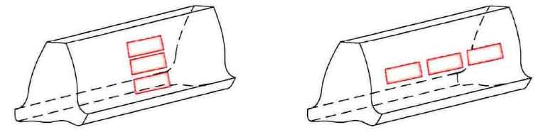
The multi-point erosion model can be mainly divided into the direction along the tooth profile and the direction along the tooth width. The establishment of the multi-point erosion model in this section considers its regular distribution instead of the random distribution of pitting positions, as shown in Fig. 1. As shown in Fig. 1 (a), the mathematical model of the distribution of multi-rectangular pitting pits along the direction of tooth profile can be composed of parallel and simple superposition of single pitting models. The calculation and analysis of meshing stiffness can be carried out by changing the range of Xi∈[Xs_st,Xs_ed], and derivation is not required here. For as shown in figure 1 (b) along tooth width direction of the rectangular pit corrosion pit distribution, assuming more erosion along tooth width direction in the direction of the tooth profile values range Xi ∈ Xs_st, Xs_ed same, tooth width multipoint corrosion coexist under the cross-sectional area and moment of inertia will also change, this is to use a single point corrosion cannot simple superposition of simulation, so the following along tooth width direction more erosion model is the mathematical equation is deduced.

The cross-section expansion of the multi-point erosion model along the tooth width direction is shown in Fig. 2. Assuming that the value range of the pitting model in the tooth profile direction Xi∈[Xs_st,Xs_ed] is the same, taking three rectangular pitting pits as an example, the mathematical expression of any rectangular pitting in the ZOY plane is:
Where I = 1,2,3. Represent the mathematical functions of rectangular pitting 1, 2 and 3, respectively.
Then, the area ASI of any rectangular pit is derived by numerical integration, and its expression is as follows:
Then it can be deduced that the cross-sectional area Ax at the engagement point Xs is:
The barycenter of any rectangular pitting pit is the formula. Since the section under lossless conditions is relative to the Z axis and the Y axis, the corresponding barycenter is the origin of the coordinate (0,0). The centroid of the section under multi-point erosion can be deduced according to the calculation formula of the centroid coordinate of the combined figure, as shown in the formula.
According to the parallel shift axis theorem, the moment of inertia of the cross-section of the multi-point etching model with respect to centroid ZSC axis can be calculated as:
The contact tooth width under rectangular multi-point etching can be expressed as:
Multi-point boundary corrosion pit into Xi ∈ [Xs_st Xs_ed] cross-sectional area and moment of inertia and contact tooth width length into formula respectively, and the joint stiffness matrix formula, as shown in formula of single and double meshing stiffness calculation formula for gear time-varying meshing stiffness analysis, in order to reduce the repetitive writing, more corrosion model analytic equation of repeated written expression no longer. For the pitting morphology with more than 3 pitting pit features along the tooth width direction, the above derivation formula can also be used for the study and analysis of meshing stiffness. It is necessary to replace the above values of I with I = 1,2,3… N, the approximate simulation calculation of multi-point erosion characteristics can be carried out.