1. Introduction
Permanent magnet gears have attracted significant attention in recent years due to their unique advantages such as contact – less transmission, high torque density, and high efficiency. This article focuses on a novel multi – shaft ring – plate permanent magnet gear (MRMG), which is designed to overcome the limitations of traditional permanent magnet gears.
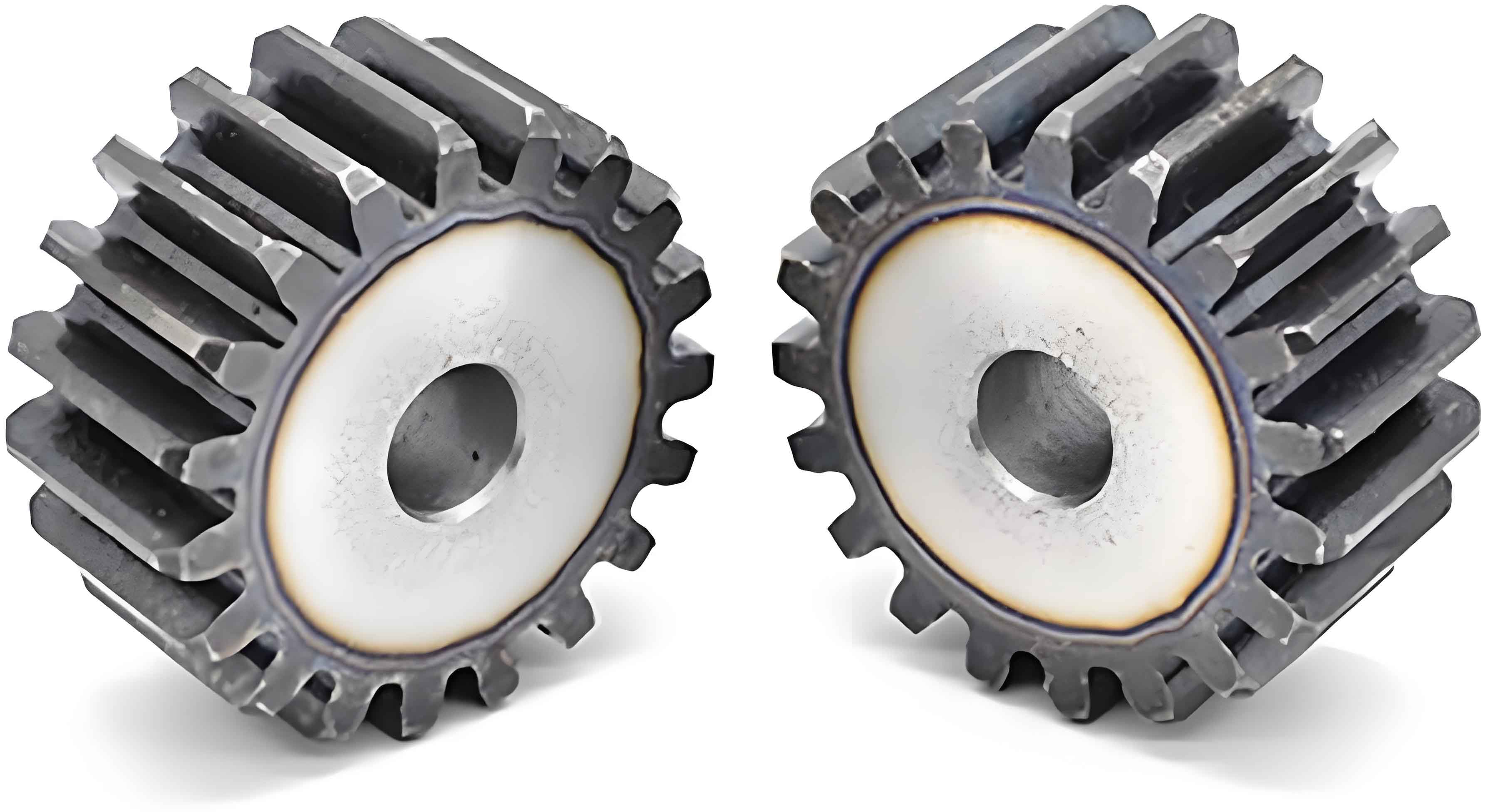
As shown in Figure 1, the MRMG consists of an inner permanent magnet ring, an outer permanent magnet ring (ring – plate), a central shaft, and multiple eccentric shafts. The inner permanent magnet ring is composed of an inner permanent magnet, a yoke, and a central shaft, while the outer permanent magnet ring is made up of an outer permanent magnet, a yoke, and eccentric shafts. The eccentric shafts are evenly distributed along the circumference of the outer yoke, and their to the inner permanent magnet ring’s central shaft distance is equal. This structure allows the outer permanent magnet ring to perform a around the inner permanent magnet ring, driving the inner permanent magnet ring to rotate.
2. Operating Mechanism of MRMG
2.1 Movement Relationship
The movement of MRMG is complex. When the inner permanent magnet ring rotates, it generates an eccentric magnetic field. Let the number of pole pairs of the inner and outer permanent magnet rings be and respectively, and the angular velocities be and . The magnetic deflection angle is formed due to the relative movement of the two rings, and it can be expressed by the formula (). This magnetic deflection angle is crucial as it affects the magnetic field distribution and torque transmission in the MRMG.
2.2 Torque and Speed Ratio
Based on the movement relationship, the torque and speed ratio of MRMG can be derived. The torque balance equations for the inner and outer permanent magnet rings and the eccentric shafts are established. Let the electromagnetic torque on the outer boundary of the inner permanent magnet ring be , and the torques of the outer permanent magnet ring and the eccentric shaft be and respectively. The 转动惯量 of the outer permanent magnet ring and the eccentric shaft are and , and the output angular velocity of the eccentric shaft is . The relationships between torque and speed are shown in the following equations.
3. Air – gap Magnetic Field and Torque Calculation of MRMG
3.1 Air – gap Magnetic Field
To calculate the air – gap magnetic field of MRMG, we first establish fixed coordinate systems and with the centers and as the origins respectively. The motion relationships between the radial and circumferential coordinates of the two coordinate systems are given by a set of equations.
The magnetization intensities of the inner and outer permanent magnets are and , which can be expressed in a series form. The regions where the inner and outer permanent magnets are located satisfy the Poisson equation of the constant magnetic field, and the air – gap region satisfies the Laplace equation. By using the boundary conditions of the magnetic field continuity at the interface between the permanent magnet and the air – gap, we can obtain the relationships between the radial and tangential air – gap magnetic densities , and the magnetic deflection angle in the non – eccentric case.
However, these magnetic densities are based on different coordinate systems and cannot be directly used to calculate the eccentric air – gap magnetic density of MRMG. Therefore, the fractional linear transformation method is employed. As shown in Figure 2, through translation, inversion, and scaling transformations, the eccentric magnetic field in the original plane is transformed into a concentric magnetic field in the complex plane.
3.2 Electromagnetic Torque and Electromagnetic Force
The electromagnetic torque and force of MRMG can be calculated using the Maxwell stress tensor method. The radial and tangential electromagnetic forces and on the inner permanent magnet ring are calculated by integrating the square of the magnetic density in the air – gap. The electromagnetic torque of the inner permanent magnet ring is obtained by taking the moment of the tangential electromagnetic force.
For the outer permanent magnet ring and the eccentric shafts, the electromagnetic force balance equations are established. The forces on each eccentric shaft are related to the forces on the inner permanent magnet ring and the motion state of the outer permanent magnet ring. Table 2 summarizes the calculation formulas for the air – gap magnetic field, electromagnetic torque, and electromagnetic force.
3.3 Transmission Loss
The transmission loss of MRMG mainly includes eddy – current loss and mechanical loss . The eddy – current loss occurs in the permanent magnets and yokes of the inner and outer permanent magnet rings. It is calculated based on the induced voltage, resistance, and cross – sectional area of the components. The mechanical loss mainly comes from the rolling and sliding friction of the arm bearings.
The eddy – current loss is the sum of the eddy – current losses in the inner and outer permanent magnet rings and yokes. The mechanical loss can be calculated according to the friction torque of the arm bearings and the angular velocity of the outer permanent magnet ring. The transmission efficiency of MRMG is defined as . Table 3 shows the calculation formulas for transmission loss and efficiency.
4. Finite Element Analysis of MRMG
4.1 Steady – state Analysis
A finite element model of MRMG is established with specific parameters (as shown in Table 4). To verify the correctness of the air – gap magnetic field calculation method, the radial and tangential air – gap magnetic densities at the center of the air – gap are calculated by the finite element method and the theoretical method.
Table 4: MRMG Model Parameters
| Model Parameter | Value |
|---|---|
| Inner permanent magnet pole pairs | 22 |
| Outer permanent magnet pole pairs | 23 |
| Outer yoke (ring – plate) inner diameter (mm) | 96 |
| Outer permanent magnet outer radius (mm) | 100 |
| Outer permanent magnet inner radius (mm) | – |
| Inner permanent magnet outer radius (mm) | 90 |
| Inner permanent magnet inner radius (mm) | 84 |
| Inner yoke inner diameter (mm) | 88 |
| Eccentricity of inner and outer permanent magnet rings (mm) | 3 |
| Axial length (mm) | 30 |
| Remanence of permanent magnet (T) | 1.25 |
| Number of eccentric shafts | 3 |
| Resistivity of permanent magnet () | |
| Resistivity of iron () | |
| Arm bearing model | 6005 – 2RS |
The results show that both the finite – element – calculated and theoretically – calculated and are 23 – order eccentric harmonic curves. As the air – gap length increases, decreases and increases. The average error between the two methods is within 4%, which verifies the correctness of the established air – gap magnetic field model.
The inner permanent magnet ring torque and radial electromagnetic force are also calculated and compared. The average error between the theoretical and finite – element results is within 5%, further validating the established torque and force calculation models.
4.2 Dynamic Analysis
In the dynamic analysis, the inner permanent magnet ring rotates at a constant speed, and the outer permanent magnet ring is under linear loading. The dynamic model of MRMG is established, and the curves of speed and torque during the dynamic process are obtained by simulation and theoretical calculation.
The results show that during the start – up process of MRMG, the speed and torque fluctuate greatly. As the running time increases, the fluctuation amplitudes gradually decrease and finally converge to the target values. The average error between the finite – element simulation curve and the theoretical model curve is within 7%, which is mainly caused by the mechanical loss of the arm bearings not considered in the finite – element simulation. This verifies the correctness of the established dynamic model.
4.3 Eddy – Current Loss Analysis
The eddy – current loss of MRMG is calculated by the theoretical formula and finite – element simulation. The results show that the value of increases with the increase of the speed of the outer permanent magnet ring . The average error between the theoretical value and the finite – element simulation value is within 5%, which validates the correctness of the eddy – current loss calculation formula.
5. Dynamic Loading Experiment of MRMG
5.1 Experimental Setup
An experimental prototype of MRMG with three eccentric shafts is developed according to the given parameters. The dynamic loading experimental device consists of a driving motor, input – end speed and torque sensors, an experimental prototype, output – end speed and torque sensors, three permanent – magnet synchronous generators, and three sets of Y – type symmetric load resistors, as shown in Figure 3.
5.2 Experimental Results and Analysis
MRMG has two transmission modes: “single – input/single – output” and “single – input/multi – output”. In the experiment, the speed ratio , torque ratio , transmission loss , and efficiency under different transmission modes are measured and analyzed.
| Transmission Mode | (r/min) | (W) | (%) |
|---|---|---|---|
| Single – input/multi – output (equal load on each eccentric shaft) | 1.66 – 6.07 | 0.61 – 3.82 | 87.17 – 92.70 |
| Single – input/multi – output (unequal load on each eccentric shaft) | 1.59 – 6.06 | 0.79 – 4.35 | 73.55 – 83.80 |
| Single – input/single – output | 1.46 – 6.06 | 0.92 – 6.87 | 54.39 – 68.30 |
It can be seen from the table that the efficiency increases with the increase of and . This is because when the resistance value is constant, the back – EMF and output current of the permanent – magnet synchronous generator are linearly related to , and the load torque provided by the resistor is also proportional to . As a result, increases with , and compared with the increase rate of , the increase rates of and with are relatively small, so shows an upward trend.
In addition, when (only 23% of the peak), the of MRMG in different transmission modes is all > 70%, while for the CMG in references [13, 20], when it exceeds 33% of the peak torque, is only > 45%. The reason is that the arm bearing of CMG needs to bear large radial and tangential forces caused by the eccentric air – gap magnetic field and a very small eccentricity simultaneously, and its pin – hole – type output mechanism has sliding friction, resulting in a large total load on the arm bearing and relatively small . In contrast, MRMG not only cancels the output mechanism of CMG but also reduces the total load on the arm bearing through multiple external eccentric shafts, so of MRMG is higher than that of CMG under various load conditions.
By comparing different transmission modes, it is found that the “single – input/multi – output” mode with equal load on each eccentric shaft has the highest efficiency. The maximum measured in this mode is 92.70%, while in the “single – input/single – output” mode, is only 68.30%, which is only 73.68% of the optimal mode. This is because in the “single – input/multi – output” mode with equal load, the outer permanent – magnet ring is evenly stressed, while in the “single – input/single – output” mode, only one eccentric shaft bears the torque, causing the outer permanent – magnet ring to be unbalanced and the other eccentric shafts to bear large force fluctuations due to . According to the formula is positively correlated with , so the in this mode is large.
When the loads on the eccentric shafts are different in the “single – input/multi – output” mode, reducing the differences in , , and can not only reduce the unbalanced stress state of the outer permanent – magnet ring but also reduce the force fluctuations of and the value of , thereby improving the efficiency of MRMG in various power ranges. That is, the “single – input/multi – output” mode with equal load on each eccentric shaft is the best operating state of MRMG.
The experimental results also show that the eddy – current loss accounts for a small proportion () in . This is because the relative speed between the inner and outer permanent – magnet rings is low due to the pendulum motion of the outer permanent – magnet ring, resulting in a small speed at which the permanent magnets in the inner and outer permanent – magnet rings cut the magnetic field.
The measured and in different operating modes have an average error of and respectively compared with the theoretical model in the “single – input/multi – output” mode, and and respectively in the “single – input/single – output” mode. These errors are mainly due to the actual assembly accuracy of the prototype and sensor sampling errors not considered in the model. However, the trends of and obtained from theoretical analysis in different operating modes are the same as the measured results, indicating that the established model is applicable to analyze the full – condition dynamic operation process of MRMG.
6. Conclusion
In conclusion, the multi – shaft ring – plate permanent – magnet gear (MRMG) has several distinct characteristics and advantages:
- The non – uniform air – gap length of MRMG has a time – varying cosine property. It can modulate the magnetic fields of the permanent magnets with different pole pairs of the inner and outer permanent – magnet rings into the same pole harmonic number for speed and torque transmission. When a set of magnets on the inner and outer permanent – magnet rings deviates from the equilibrium path with another set of magnets, a magnetic deflection angle is formed. This angle adjusts the air – gap magnetic density and promotes the re – equilibrium of the air – gap magnetic field in MRMG. Therefore, all quantifiable mathematical models and transmission characteristics are functions of the angle.
- MRMG can be divided into one and two By using the continuity of the permanent – magnet magnetic field in the air – gap, the and the are connected. Thus, the eccentric air – gap magnetic field equations of the inner and outer permanent – magnet rings are obtained. Through the fractional linear transformation, the eccentric magnetic field can be transformed into a concentric magnetic field, and the air – gap magnetic density, electromagnetic torque, and the electromagnetic force balance equations of each eccentric shaft under this magnetic field can be obtained.
- The effective coupling area of the inner and outer permanent – magnet rings of MRMG accounts for more than 2/3 of the total magnetic ring area, and each permanent – magnet can participate in the generation of the air – gap magnetic field and torque transmission. Therefore, MRMG has a high – torque – density characteristic (about ). In addition, when operating stably, there is almost no speed difference between the inner and outer permanent – magnet rings, so the eddy – current loss formed by the permanent magnets and yokes is small ( of ).
- MRMG has two transmission modes: “single – input/single – output” and “single – input/multi – output”. In the “single – input/single – output” mode, only one eccentric shaft bears the torque, resulting in an unbalanced stress state of the outer permanent – magnet ring and large radial force fluctuations of each eccentric shaft. This mode has high power loss and low transmission efficiency. In the “single – input/multi – output” mode, since each eccentric shaft participates in torque transmission, the stress distribution of the outer permanent – magnet ring is uniform, so it has smaller force fluctuations and higher transmission efficiency compared with the “single – input/single – output” mode.
- In the “single – input/multi – output” mode, if there are deviations between the loads of the eccentric shafts, the differences should be reduced as much as possible to minimize the power loss of the internal branches. When the load differences cannot be changed, the total load torque should be increased as much as possible to improve the transmission efficiency. Among these transmission modes, the “single – input/multi – output” mode with equal load on each eccentric shaft is the optimal, followed by the mode where each eccentric shaft bears a load but there are load deviations, and the “single – input/single – output” mode has the lowest transmission efficiency. The highest measured efficiency of the “single – input/single – output” mode is only 73.68% of the optimal mode.