
The three-dimensional tooth digital model is obtained through reverse engineering modeling. The digital model only includes tooth width, face cone, root cone, back cone and reference cylinder, and there is no addendum rounding model. To import the mathematical model into UG software, it is necessary to apply UG software CAD module to carry out spiral bevel gear tooth top rounding processing and complete the establishment of spiral bevel gear tooth top rounding digital model, as shown in Figure 1.

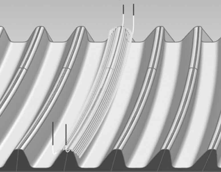
As the material of the part is alloy steel 9310, and the hardness of the tooth surface of spiral bevel gear after carburizing is hra81 ~ 83, it is hardened alloy steel, which needs to be processed with a tool specially for processing hardened materials. Therefore, according to the actual working conditions, the tool diameter is φ 4. Machining with integral cemented carbide ball end milling cutter. The cam module of UG software is applied to select the reasonable cutting mode, one-time feed and discharge, and the reciprocating processing path is adopted. The processing path is simple, which avoids the problem of tool marks affecting the surface quality caused by multiple feed and discharge, and saves the processing time. The tool path of five axis NC program is shown in Figure 2.
The corresponding five axis machine tool post-processing is applied to generate the machine tool identification program, and VERICUT software is used for machining simulation to verify the correctness of the program and the interference and collision.
Complete the part installation and zero point setting, install the part on the workbench, locate the end face, select the installation distance from the end face, and complete the workpiece coordinate system setting. Then carry out trial cutting. After the rounding of the tooth top of the first spiral bevel gear is completed, observe the rounding position. If the tooth surface of the left spiral bevel gear is over cut with the rounding, the c axis rotates a certain angle in the negative direction, otherwise it rotates in the positive direction. Until the tooth surface, tooth crest and rounding cutter of spiral bevel gear are smooth, at this time, the position of axis C coincides with the programmed coordinate system.

After adjusting the angular position, complete the tooth rounding of all spiral bevel gears. The machining test was carried out on the five axis machining center dmu80p. The finished part rounding is tangent to the tooth surface and tooth top of spiral bevel gear, without tool receiving trace, and the rounding roughness reaches Ra0 4. The rounding deviation is less than 0.1mm, which meets the design requirements, and the rounding test is successful. The physical parts are shown in Figure 3.