
I design screw gears as threaded power-transfer pairs that convert rotation into straight-line motion, and I also treat the same term as the core meshing element in a broader family of helical and threaded drives. In my networked design approach, screw gears are no longer handled through scattered manual tables, hand calculations, and isolated experience. Instead, I combine a browser/server architecture, a remote database, and ASP.Net technology so that a designer can enter parameters in a web page and receive a complete screw gears design result online. My objective is to make screw gears design faster, more accurate, more traceable, and more repeatable.
The traditional process for screw gears is time-consuming because the designer must search manuals, interpolate values, calculate several interdependent quantities, verify strength, check stability, and then repeat the process when one parameter changes. I have found that this manual loop is especially inefficient when the design involves multiple screw gears candidates, different materials, or varying axial loads. My system replaces that loop with a guided web workflow. The designer supplies the initial conditions, the system propagates the data, and the verification module evaluates the screw gears against wear, efficiency, buckling, critical speed, and thermal limits.
1. Why I Network Screw Gears Design
I see screw gears as a class of transmission elements that benefit strongly from network-based design because their behavior depends on a chain of parameters. A change in lead, pitch diameter, thread height, number of starts, friction coefficient, or support length can alter the entire screw gears result. In a manual process, this chain is often broken by transcription errors. In my networked system, the chain is preserved as a digital data flow.
The main motivations for my work are summarized in the following table.
| Motivation | Manual screw gears design | My networked screw gears design |
|---|---|---|
| Data retrieval | Search paper manuals and catalogs | Query a remote database in the browser |
| Calculation | Hand calculation or local spreadsheet | Server-side calculation with reusable formulas |
| Accuracy | Depends on user skill and attention | Controlled by validation rules and checks |
| Repeated design | Redo most steps after a parameter change | Backtracking and automatic propagation |
| Collaboration | Files are copied and versions diverge | Central remote database and session cache |
| Traceability | Notes may be incomplete | Stored inputs, outputs, and verification states |
| Access | Requires local software and references | Requires only a browser and network access |
I use the term screw gears repeatedly because the design object is not a single screw in isolation. It is the complete engagement between the threaded screw and the nut, together with the supports, lubrication, materials, and duty cycle. When I model screw gears, I consider the screw gears as a system: geometry, kinematics, friction, load capacity, stability, and thermal behavior.
2. Architecture I Use for Screw Gears
My system follows a browser/server structure. The browser is the thin client. The web server hosts the application logic, the calculation engine, and the page controls. The database server stores materials, thread standards, design records, user sessions, and validation rules. This separation is important for screw gears because the calculation engine can be updated centrally without requiring every designer to install new software.
| Layer | Role in my screw gears system | Typical technology |
|---|---|---|
| Presentation layer | Guided pages, forms, tables, validation messages | HTML, ASP.Net controls, CSS, JavaScript |
| Application layer | Workflow, backtracking, calculation, verification | C#, ASP.Net, server-side logic |
| Data layer | Materials, standards, inputs, results, rules | Remote relational database |
| Session layer | Temporary screw gears parameters and backtracking stack | Cookies, server cache, session state |
| Communication layer | Browser requests and server responses | HTTP or HTTPS, B/S network structure |
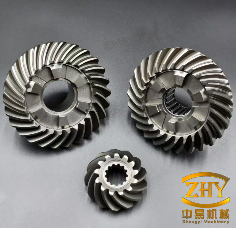
In my architecture, screw gears data can be read from the remote database without installing a local database. A designer opens the browser, logs in, and selects the screw gears type. The server then loads default values, recommended materials, and prior design records. This makes the screw gears design process remote, centralized, and consistent.
3. Functional Modules of My Screw Gears System
I divide the system into three primary modules: design workflow, data management, and verification. Each module has a specific responsibility for screw gears.
| Module | Function | How it supports screw gears |
|---|---|---|
| Design workflow | Step-by-step design | Guides the user from initial conditions to final screw gears dimensions |
| Data management | Query, explanation, transmission | Provides material data, thread standards, and parameter storage for screw gears |
| Verification | Calculation and checking | Evaluates wear, efficiency, buckling, speed, and thermal limits of screw gears |
3.1 Design Workflow Module
The design workflow module leads the user through a sequence of pages. I designed each page to contain only the parameters needed for the current screw gears step. The user enters values, submits the form, and the server returns the next step. Every adjacent step has a backtracking mechanism. If the user changes an earlier screw gears parameter, later results are cleared or recalculated so that inconsistent data does not remain in the session.
3.2 Data Management Module
The data management module performs query, explanation, and transmission. Query retrieves existing screw gears parameters from the database for review or comparison. Explanation provides notes about design details, such as allowable pressure, lubrication, and thread selection. Transmission moves parameters to the database or session cache so that later screw gears steps can use them.
3.3 Verification Module
The verification module reduces calculation errors and quality loss caused by manual work. It consists of computation and checking. For screw gears, I compute the main geometric and mechanical quantities, then I check them against allowable limits. If a check fails, the system informs the user and guides the user back to the relevant screw gears step.
4. Design Workflow for Screw Gears
I structure the screw gears workflow so that the user always knows the current state and the next action. The general sequence is shown below.
| Step | Input or decision | Output for screw gears |
|---|---|---|
| 1 | User information and session start | Session identity and working context |
| 2 | Select screw gears type | Sliding screw gears, rolling screw gears, or another category |
| 3 | Initial conditions | Axial load, speed, stroke, duty, accuracy, environment |
| 4 | Material and thread standard | Screw material, nut material, friction pair, thread series |
| 5 | Preliminary geometry | Pitch diameter, lead, starts, thread height |
| 6 | Wear calculation | Contact pressure and allowable pressure comparison |
| 7 | Efficiency calculation | Lead angle, friction angle, efficiency |
| 8 | Stability calculation | Critical load and safety factor |
| 9 | Critical speed calculation | Speed margin for screw gears |
| 10 | Thermal calculation | Temperature rise and heat balance |
| 11 | Summary | Final screw gears dimensions and verification report |
I make the workflow cyclic rather than strictly linear. If a verification step fails, the user can return to an earlier screw gears page, modify the required parameter, and rerun the downstream calculations. The system does not force the user to restart the entire screw gears project unless the selected type itself changes.
5. Mathematical Models for Screw Gears
I use standard mechanical relationships to model screw gears. The notation I apply is listed below.
| Symbol | Meaning | Unit |
|---|---|---|
| \(F\) | Axial load on screw gears | N |
| \(T\) | Input torque | N·m |
| \(n\) | Rotational speed | r/min |
| \(v\) | Linear speed | m/min |
| \(p_h\) | Lead of screw gears | mm |
| \(p_x\) | Pitch | mm |
| \(z\) | Number of starts | — |
| \(d_2\) | Pitch diameter | mm |
| \(d\) | Nominal diameter | mm |
| \(h\) | Thread height | mm |
| \(\lambda\) | Lead angle | rad or degree |
| \(\rho\) | Friction angle | rad or degree |
| \(\eta\) | Efficiency | — |
| \(p\) | Contact pressure | MPa |
| \([p]\) | Allowable pressure | MPa |
| \(E\) | Elastic modulus | MPa |
| \(I\) | Second moment of area | mm^4 |
| \(l\) | Unsupported length | mm |
| \(\mu\) | End-condition coefficient | — |
The kinematic relation for screw gears is:
$$v=\frac{p_h n}{60}$$
Rearranged for speed, I obtain:
$$n=\frac{60v}{p_h}$$
The lead is related to the pitch and number of starts by:
$$p_h = z p_x$$
The lead angle of screw gears is:
$$\lambda=\arctan\left(\frac{p_h}{\pi d_2}\right)$$
The friction angle is:
$$\rho=\arctan f$$
Where \(f\) is the friction coefficient of the screw gears pair. The efficiency for power screw gears is:
$$\eta=\frac{\tan\lambda}{\tan(\lambda+\rho)}$$
The input torque required for screw gears is approximately:
$$T=\frac{F p_h}{2\pi \eta}$$
The contact pressure on the threads of screw gears is:
$$p=\frac{F}{\pi d_2 h z}\le [p]$$
The critical buckling load for a screw gears member is:
$$F_c=\frac{\pi^2 E I}{(\mu l)^2}$$
The stability safety factor is:
$$S=\frac{F_c}{F}$$
The critical speed of screw gears is estimated by:
$$n_c=\frac{60 k^2}{2\pi l^2}\sqrt{\frac{E I}{\rho_m A}}$$
Where \(k\) is a support-condition coefficient, \(\rho_m\) is material density, and \(A\) is the cross-sectional area. For a circular screw gears section:
$$I=\frac{\pi d^4}{64}$$
$$A=\frac{\pi d^2}{4}$$
I use these formulas as the core of my calculation engine. Each formula is stored as a server-side function, and each result is written to the session data for later screw gears steps.
6. Remote Database and Data Management for Screw Gears
I use a remote database so that screw gears data is centralized. The user does not need to install a local database. The browser connects to the application, and the application connects to the database. This is especially useful when several designers work on screw gears projects because they all read from the same standards and material tables.
| Table | Purpose | Representative fields |
|---|---|---|
| sg_materials | Store screw gears materials | material_id, name, E, yield_strength, density, allowable_pressure |
| sg_thread_standards | Store thread series for screw gears | standard_id, nominal_diameter, pitch, lead, thread_height |
| sg_design_inputs | Store user inputs for screw gears | session_id, axial_load, speed, stroke, duty_cycle, accuracy |
| sg_design_results | Store calculated screw gears results | session_id, lead_angle, efficiency, pressure, safety_factor |
| sg_validation_rules | Store checking rules for screw gears | rule_id, parameter, min_value, max_value, message |
| sg_user_sessions | Track active screw gears sessions | session_id, user_name, start_time, last_step |
| sg_backtrack_stack | Record backtracking history for screw gears | session_id, step_order, parameter_name, old_value |
| sg_parameter_cache | Cache temporary screw gears parameters | session_id, key, value, expiration |
I use ASP.Net controls such as TreeView, DataList, and DataGrid to present database records. TreeView is useful for screw gears categories and design steps. DataList is useful for material cards and thread options. DataGrid is useful for comparing multiple screw gears candidates and verification results.
| Control | Use in screw gears design | Benefit |
|---|---|---|
| TreeView | Show screw gears type hierarchy and workflow steps | Clear navigation and backtracking access |
| DataList | Display materials, lubricants, and thread standards | Compact browsing of screw gears options |
| DataGrid | Compare screw gears candidates and check results | Fast comparison and selection |
The database also stores explanation content. When the user is unsure about a screw gears parameter, the explanation function retrieves notes from the database. This reduces training time and prevents misuse of screw gears data.
7. User Guidance and Backtracking for Screw Gears
I designed the interface around user guidance. The page is divided into a workflow area and a working area. The workflow area shows the current screw gears step and the next step. The working area contains the form, the calculation results, and the verification messages. Buttons for explanation and confirmation help the user proceed safely.
Backtracking is essential for screw gears because design is iterative. If the user changes the axial load, the wear pressure, efficiency, torque, and stability factor all change. My backtracking mechanism clears downstream screw gears results and recalculates them when the user proceeds again.
| Backtracking action | Effect on screw gears data | System response |
|---|---|---|
| Return to initial conditions | Clears geometry, pressure, efficiency, stability, speed | Shows confirmation dialog |
| Return to material selection | Clears allowable pressure, friction, efficiency, checks | Reloads material options |
| Return to geometry | Clears pressure, efficiency, stability, speed | Recalculates after confirmation |
| Return to wear calculation | Clears efficiency, stability, speed, thermal | Keeps earlier screw gears inputs |
| Return to verification | Keeps all inputs, reruns checks | Displays updated screw gears status |
I use dependency tracking to decide what to clear. For example, if the lead changes, the lead angle, efficiency, torque, and linear speed relation change. If the nominal diameter changes, the section area, inertia, buckling load, and critical speed change. The dependency table is shown below.
| Changed parameter | Affected screw gears quantities |
|---|---|
| Lead \(p_h\) | Lead angle, efficiency, torque, linear speed, thermal load |
| Pitch diameter \(d_2\) | Lead angle, contact pressure, efficiency, inertia, critical speed |
| Axial load \(F\) | Torque, contact pressure, safety factor, thermal load |
| Rotational speed \(n\) | Linear speed, thermal load, critical speed margin |
| Material | Allowable pressure, friction coefficient, efficiency, stability |
| Support length \(l\) | Buckling load, safety factor, critical speed |
| End condition \(\mu\) | Buckling load, safety factor, critical speed |
8. Data Transmission with Cookies in My Screw Gears System
I use cookies to transmit temporary screw gears parameters between pages. A cookie is a small data record stored by the browser. It is convenient for retaining the current screw gears context without writing every intermediate value to the database. I also use server-side cache for larger or more sensitive screw gears data.
| Operation | Purpose in screw gears workflow | Typical content |
|---|---|---|
| Create cookie | Start a new screw gears session | Session identifier, step name, timestamp |
| Write value | Store current screw gears parameter | Lead, diameter, load, speed, material code |
| Read value | Retrieve parameter for next step | Previously entered screw gears data |
| Update value | Replace a screw gears parameter after backtracking | New lead or new axial load |
| Remove value | Clear downstream screw gears results | Efficiency, pressure, safety factor |
| Expire cookie | End an inactive screw gears session | Session timeout |
My cookie flow follows these steps:
$$ \text{create cookie} \rightarrow \text{initialize memory} \rightarrow \text{write parameter} \rightarrow \text{read parameter} \rightarrow \text{update or remove} \rightarrow \text{expire} $$
For screw gears, I keep the cookie small. Large tables and long verification logs are stored in the remote database or server cache. The cookie stores only keys and short values. This keeps the screw gears workflow responsive and reduces the risk of losing data during page transitions.
9. Verification and Checking of Screw Gears
I consider verification to be the most important part of the system. A screw gears design can appear correct geometrically but fail in service due to wear, buckling, critical speed, or overheating. My verification module checks each of these conditions.
| Check | Condition for screw gears | Action if failed |
|---|---|---|
| Wear | \(p \le [p]\) | Increase diameter, lead, thread height, or number of starts |
| Efficiency | \(\eta \ge \eta_{\min}\) | Change lead angle, friction pair, or lubrication |
| Self-locking | \(\lambda \le \rho\) when required | Adjust lead or friction condition |
| Buckling | \(S=F_c/F=2.5\sim4\) | Increase diameter, reduce unsupported length, change support |
| Critical speed | \(n < n_c / S_n\) | Change diameter, support, or operating speed |
| Thermal | \(\Delta T \le \Delta T_{\max}\) | Improve lubrication, reduce speed, reduce load |
For wear, I use the pressure formula already introduced:
$$p=\frac{F}{\pi d_2 h z}\le [p]$$
For buckling, I compare the critical load with the axial load:
$$S=\frac{F_c}{F}=\frac{\pi^2 E I}{(\mu l)^2 F}$$
For critical speed, I require a margin:
$$n \le \frac{n_c}{S_n}$$
For thermal behavior, I estimate the heat generated by friction:
$$Q=F v (1-\eta)$$
The temperature rise is:
$$\Delta T=\frac{Q}{K_t A_t}$$
Where \(K_t\) is the heat transfer coefficient and \(A_t\) is the heat dissipation area. I include this check because high-speed screw gears can lose lubrication effectiveness and change clearance if the temperature rise is excessive.
10. Case Study of a Screw Gears Design
I now demonstrate a simple screw gears case to show how the system works. The inputs are listed below.
| Parameter | Value | Unit |
|---|---|---|
| Axial load \(F\) | 5000 | N |
| Linear speed \(v\) | 0.5 | m/min |
| Nominal diameter \(d\) | 40 | mm |
| Pitch \(p_x\) | 6 | mm |
| Number of starts \(z\) | 1 | — |
| Pitch diameter \(d_2\) | 37 | mm |
| Thread height \(h\) | 3 | mm |
| Friction coefficient \(f\) | 0.12 | — |
| Allowable pressure \([p]\) | 18 | MPa |
| Unsupported length \(l\) | 800 | mm |
| End-condition coefficient \(\mu\) | 0.7 | — |
| Elastic modulus \(E\) | 210000 | MPa |
First, I calculate the lead of the screw gears:
$$p_h = z p_x = 1 \times 6 = 6 \text{ mm}$$
Next, I calculate the rotational speed:
$$n=\frac{60v}{p_h}=\frac{60 \times 0.5}{6}=5 \text{ r/min}$$
Then I calculate the lead angle:
$$\lambda=\arctan\left(\frac{p_h}{\pi d_2}\right)=\arctan\left(\frac{6}{\pi \times 37}\right) \approx 2.95^\circ$$
The friction angle is:
$$\rho=\arctan(0.12) \approx 6.84^\circ$$
The efficiency of the screw gears is:
$$\eta=\frac{\tan\lambda}{\tan(\lambda+\rho)}=\frac{\tan(2.95^\circ)}{\tan(9.79^\circ)} \approx 0.299$$
The input torque is:
$$T=\frac{F p_h}{2\pi \eta}=\frac{5000 \times 0.006}{2\pi \times 0.299} \approx 15.96 \text{ N·m}$$
The contact pressure is:
$$p=\frac{F}{\pi d_2 h z}=\frac{5000}{\pi \times 37 \times 3 \times 1} \approx 14.3 \text{ MPa}$$
Since \(14.3 \text{ MPa} \le 18 \text{ MPa}\), the wear check passes. The efficiency of \(0.299\) is low but acceptable for a self-locking or slow-speed screw gears pair. I note that if the application requires higher efficiency, the lead angle must increase.
For buckling, I calculate the second moment of area:
$$I=\frac{\pi d^4}{64}=\frac{\pi \times 40^4}{64} \approx 125664 \text{ mm}^4$$
The critical load is:
$$F_c=\frac{\pi^2 E I}{(\mu l)^2}=\frac{\pi^2 \times 210000 \times 125664}{(0.7 \times 800)^2} \approx 830580 \text{ N}$$
The safety factor is:
$$S=\frac{F_c}{F}=\frac{830580}{5000} \approx 166$$
This is far above the recommended range of \(2.5\) to \(4\). The screw gears are therefore very safe against buckling in this case. If the value were too high, I could reduce the diameter or increase the unsupported length, but that would affect other screw gears checks.
The thermal load is:
$$Q=F v (1-\eta)$$
Using \(v=0.5/60 \text{ m/s}\) for consistent units:
$$Q=5000 \times \frac{0.5}{60} \times (1-0.299) \approx 29.2 \text{ W}$$
This heat is modest, so the thermal check passes under normal lubrication. If the speed or load were higher, I would increase the heat dissipation area or improve lubrication.
| Result | Value | Status |
|---|---|---|
| Lead | 6 mm | Accepted |
| Rotational speed | 5 r/min | Accepted |
| Lead angle | 2.95° | Accepted |
| Efficiency | 0.299 | Accepted for low-speed screw gears |
| Torque | 15.96 N·m | Accepted |
| Contact pressure | 14.3 MPa | Passed |
| Buckling safety factor | 166 | Passed |
| Thermal load | 29.2 W | Passed |
From this case, I can see how a single change affects the screw gears system. If I increase the axial load to 8000 N, the pressure becomes 22.9 MPa, which exceeds the allowable 18 MPa. The system would then prompt me to increase the diameter, increase the number of starts, or choose a material with a higher allowable pressure. This is exactly the type of guided iteration that my networked screw gears system supports.
11. Comparison and Benefits of My Screw Gears System
I compare the traditional and networked approaches for screw gears in the table below.
| Aspect | Traditional screw gears design | My networked screw gears design |
|---|---|---|
| Startup | Collect manuals and templates | Open browser and log in |
| Parameter entry | Handwritten or local spreadsheet | Guided web forms |
| Data lookup | Manual table search | Remote database query |
| Calculation | Manual formula evaluation | Server-side calculation engine |
| Revisions | Erase and recalculate manually | Backtracking with dependency clearing |
| Checks | May be omitted or inconsistent | Automated verification for screw gears |
| Documentation | Manual notes and reports | Stored inputs, outputs, and verification states |
| Reuse | Copy old files and edit | Query past screw gears records |
| Accuracy | Depends on user | Controlled by rules and formulas |
| Speed | Slow for iterative screw gears | Fast for multiple screw gears candidates |
The benefits are clear. I reduce the time spent on routine screw gears calculations. I improve consistency by using one remote database. I reduce errors by using server-side formulas and automatic checks. I make the screw gears design process accessible from any browser. I also create a record of each screw gears design so that future projects can reuse validated parameters.
12. Extensions and Deployment of the Screw Gears System
I designed the system so that it can be extended. New screw gears types can be added by inserting new rows into the type table and adding corresponding workflow pages. New materials can be added without changing the calculation engine. New verification rules can be stored in the database and applied dynamically.
| Extension | How I implement it | Effect on screw gears design |
|---|---|---|
| New screw gears type | Add type definition and page template | Supports more screw gears variants |
| New material | Insert material properties | Expands screw gears selection |
| New standard | Add thread series rows | Improves screw gears compatibility |
| New check | Add validation rule | Strengthens screw gears verification |
| New report | Add report template | Improves screw gears documentation |
| New language | Add resource strings | Supports broader screw gears users |
For deployment, I use a web server and a database server. The web server hosts the ASP.Net application. The database server stores the screw gears data. Communication uses HTTPS where possible. User sessions are authenticated. Database queries are parameterized to reduce injection risk. Sensitive screw gears design records can be restricted by role.
| Deployment concern | My measure | Benefit for screw gears |
|---|---|---|
| Authentication | Login and session validation | Protects screw gears records |
| Authorization | Role-based access | Limits editing of standard screw gears data |
| Transport security | HTTPS | Protects screw gears parameters |
| Database security | Parameterized queries | Reduces injection risk |
| Backup | Periodic database backup | Preserves screw gears history |
| Scalability | Stateless web layer and shared database | Supports more screw gears users |
13. Practical Guidance I Give to Users of Screw Gears
I include practical notes in the system so that users do not treat screw gears as a purely mathematical object. The following guidance appears in the explanation dialogs.
| Topic | Guidance for screw gears |
|---|---|
| Lubrication | Use a lubricant compatible with the screw gears materials and operating temperature. |
| Friction | Friction affects efficiency, wear, and self-locking behavior of screw gears. |
| Lead angle | A small lead angle favors self-locking but reduces efficiency in screw gears. |
| Number of starts | More starts increase lead and speed but can reduce self-locking in screw gears. |
| Thread height | Greater thread height reduces pressure but may affect geometry and manufacturing. |
| Support | Support conditions strongly affect buckling and critical speed of screw gears. |
| Material pair | Dissimilar materials often reduce wear in screw gears. |
| Thermal | Continuous operation requires heat balance for screw gears. |
I also recommend that users compare at least two screw gears candidates. The database query function allows them to retrieve previous screw gears records and compare diameters, leads, efficiencies, and safety factors. This comparison is difficult in a manual process but straightforward in my networked system.
14. Verification Rules and Formula Summary
I summarize the main verification rules for screw gears below.
| Quantity | Formula | Acceptance condition |
|---|---|---|
| Linear speed | \(v=p_h n/60\) | Matches required motion |
| Lead | \(p_h=z p_x\) | Matches standard or custom requirement |
| Lead angle | \(\lambda=\arctan(p_h/(\pi d_2))\) | Compatible with efficiency and self-locking |
| Efficiency | \(\eta=\tan\lambda/\tan(\lambda+\rho)\) | \(\eta \ge \eta_{\min}\) |
| Torque | \(T=F p_h/(2\pi\eta)\) | Within drive capacity |
| Pressure | \(p=F/(\pi d_2 h z)\) | \(p \le [p]\) |
| Buckling load | \(F_c=\pi^2 E I/(\mu l)^2\) | \(F_c/F=2.5\sim4\) |
| Safety factor | \(S=F_c/F\) | Within recommended range |
| Critical speed | \(n_c=60k^2/(2\pi l^2)\sqrt{EI/(\rho_m A)}\) | \(n \le n_c/S_n\) |
| Heat | \(Q=F v(1-\eta)\) | \(\Delta T \le \Delta T_{\max}\) |
These rules are stored in the database as validation rules. When the user clicks the check button, the system reads the current screw gears parameters, evaluates the formulas, and compares the results with the rules. If a rule fails, the system displays a message and offers a backtracking link to the relevant screw gears step.
15. Session and Data Integrity for Screw Gears
I maintain data integrity in several ways. First, each screw gears session has a unique identifier. Second, each parameter has a defined type and range. Third, dependencies are tracked so that stale screw gears results are not used. Fourth, verification results are stored with timestamps. Fifth, the database uses constraints to prevent invalid material or standard records.
| Integrity mechanism | Implementation | Effect on screw gears data |
|---|---|---|
| Unique session | Session identifier | Separates concurrent screw gears designs |
| Type checking | Server-side validation | Prevents text in numeric screw gears fields |
| Range checking | Min/max rules | Keeps screw gears parameters realistic |
| Dependency tracking | Step graph | Clears invalid downstream screw gears results |
| Timestamping | Audit fields | Tracks changes to screw gears records |
| Foreign keys | Database constraints | Links screw gears inputs to valid standards |
I also use a temporary cache for the current screw gears calculation. When the user submits a page, the server reads the cookie, loads the cache, performs the calculation, updates the database if needed, and returns the next page. This sequence keeps the screw gears workflow fast even when the remote database is large.
16. Design Records and Reuse of Screw Gears
I store each completed screw gears design as a record. The record includes the input conditions, selected material, thread standard, calculated geometry, efficiency, pressure, safety factor, critical speed, thermal result, and verification status. The user can query these records by load range, speed, diameter, or material. This makes reuse practical.
| Record field | Description | Use in future screw gears projects |
|---|---|---|
| Project identifier | Unique design record | Traceability |
| Load | Axial load range | Select similar screw gears |
| Speed | Operating speed | Check critical speed quickly |
| Material | Screw and nut materials | Reuse proven screw gears pairs |
| Geometry | Diameter, lead, starts, thread height | Seed a new screw gears design |
| Efficiency | Calculated efficiency | Compare energy loss |
| Pressure | Contact pressure | Assess wear risk |
| Safety factor | Buckling margin | Assess stability |
| Thermal result | Temperature rise | Assess duty cycle |
| Verification status | Pass or fail | Filter valid screw gears records |
Reuse is one of the strongest advantages of my networked approach. In a manual screw gears process, old calculations are often lost or stored in a format that is difficult to search. In my system, old screw gears records become a knowledge base. A new design can start from a similar record, and the user can modify only the parameters that differ.
17. Error Prevention in Screw Gears Calculations
I prevent errors by combining server-side calculation with client-side hints. The server-side calculation is authoritative. The client-side hints help the user avoid obvious mistakes before submission. The system checks units, ranges, required fields, and logical consistency.
| Error type | Example in screw gears | My prevention method |
|---|---|---|
| Unit error | Entering speed in m/s instead of r/min | Unit labels and range checks |
| Missing value | No axial load | Required field validation |
| Impossible geometry | Thread height greater than pitch | Geometry rule |
| Wrong material | Allowable pressure too low | Material compatibility check |
| Unsafe design | Buckling safety factor below 2.5 | Verification warning |
| Stale result | Efficiency from old lead | Dependency clearing |
| Duplicate record | Same screw gears session submitted twice | Session and timestamp check |
I also include a summary page before final storage. The summary shows every screw gears parameter and every verification result. The user must confirm the summary before the record is committed to the database. This extra step catches mistakes that might otherwise be overlooked.
18. Performance and Scalability of My Screw Gears System
I designed the system to be responsive. The calculation for a single screw gears candidate is light, but comparing many candidates can become heavy. I therefore cache material and standard tables, compute only the current candidate on page submission, and use database indexes for screw gears records.
| Performance factor | My approach | Result for screw gears |
|---|---|---|
| Page load | Minimal data per step | Fast guided screw gears workflow |
| Calculation | Server-side functions | Consistent screw gears results |
| Database query | Indexed tables | Fast retrieval of screw gears standards |
| Session data | Cookie plus cache | Low overhead for screw gears parameters |
| Comparison | DataGrid with paging | Scalable screw gears candidate review |
| Storage | Normalized records | Efficient screw gears history |
For larger deployments, I can separate the web server and database server, add a load balancer, and use a distributed cache. The screw gears calculation logic remains the same, so scaling does not change the design results.
19. Conclusion
I have presented a networked design system for screw gears. The system uses a browser/server structure, ASP.Net technology, a remote database, guided web pages, backtracking, cookie-based data transmission, and automated verification. It transforms the traditional manual screw gears design process into an online workflow that is faster, more accurate, and more traceable.
My system supports the complete screw gears design chain: initial conditions, type selection, material selection, geometry, wear calculation, efficiency calculation, torque calculation, buckling check, critical speed check, thermal check, and final summary. Each screw gears parameter is stored and propagated. Each check is rule-based. Each backtracking action clears dependent results so that the user never relies on stale screw gears data.
I believe that this approach is valuable because screw gears are used in many automatic control systems, machine tools, lifting devices, and precision mechanisms. The need for rapid and reliable screw gears design will continue to grow. By moving screw gears design to the network, I make it possible for designers to access standards, perform calculations, verify results, and reuse validated records from any browser. The result is a more efficient and more reliable screw gears design process.
In future work, I will extend the system with more screw gears types, more material pairs, more standards, and more verification rules. I will also add richer comparison reports and tighter integration with computer-aided design tools. The core principle will remain the same: screw gears design should be guided, calculated, checked, and stored in a consistent digital environment.