
I designed and evaluated a drag-type carrot harvesting device in which non-circular pinion gears replace the conventional constant-speed drive. My motivation is straightforward: carrot root-stem separation is the most critical operation in carrot harvesting, and a poorly controlled drag motion causes bruising, incomplete separation, and low success rates. In my work, I treat the motion of the drag rods as the primary design target rather than as a secondary outcome of the gearbox. I use reverse analysis to link the desired drag-rod velocity curve to the pitch curves of non-circular pinion gears, then I build a three-dimensional model, run motion simulation, construct a test bench, and compare the new device with a traditional drag-type separation unit. The results show that non-circular pinion gears can improve separation success and reduce damage.
The keyword of my design is pinion gears. More precisely, it is non-circular pinion gears. Unlike ordinary circular pinion gears, non-circular pinion gears have a variable instantaneous transmission ratio. That variability allows me to shape the drag-rod velocity profile during the working window. In my view, this is the central advantage of using non-circular pinion gears in a carrot harvesting device: the gear pair itself becomes a motion-programming element. The drag rod no longer follows a simple sinusoidal velocity curve. Instead, it can accelerate quickly, reach a high speed, and remain near that high speed while it interacts with the carrot. This behavior is exactly what I want for root-stem separation.
Background and Problem Statement
Carrots are grown widely and consumed globally because of their nutritional value. In many production systems, the harvested crop must be separated from the leafy top before storage or processing. The separation step determines not only harvesting efficiency but also product quality. If the drag rod strikes too slowly, the root may not separate cleanly. If the drag rod interacts too long, the root surface may be bruised or scratched. If the speed changes too abruptly in the wrong phase, the root may be pulled at an unfavorable angle. These effects are all connected to the motion of the drag rod, and the motion of the drag rod is connected to the transmission system. Therefore, the transmission system is not a passive component. It is part of the harvesting process.
Traditional drag-type carrot harvesting devices usually use circular gears or other constant-speed transmissions. A circular pinion gear pair gives a fixed ratio, so the driven shaft rotates at a constant angular speed relative to the input. The drag rod is then driven by a rotating disc. The resulting motion is periodic and smooth, but it is not optimized for separation. In the working window, the drag-rod velocity rises gradually and never remains constant. The carrot experiences a changing force, and the separation event is not sharply localized. This is the problem I set out to solve.
Earlier work on carrot tassel mechanics showed that the drag-rod motion has a significant effect on root-stem separation. High instantaneous speed can help initiate separation. A sustained high-speed phase can help complete separation. A long low-speed phase can increase friction and bruising. These findings suggested to me that the velocity curve should be reshaped. The traditional sinusoidal curve is not ideal. An improved curve should have a rapid acceleration stage and a stable high-speed working stage. To realize that curve mechanically, I chose non-circular pinion gears.
I use the term pinion gears repeatedly because the gear pair is the heart of the mechanism. The driving pinion gear and the driven pinion gear are both non-circular. Their pitch curves are not circles. Their radii vary with rotation angle. As a result, the angular velocity of the driven pinion gear varies even when the driving pinion gear rotates uniformly. This variable output is transmitted through a reduction gear pair and a constant-speed gear pair to the drag-rod discs. In this way, non-circular pinion gears generate the desired drag-rod motion without adding complex linkages or electronic cams. The design remains mechanical, robust, and suitable for field conditions.
Working Principle of the Drag-Type Harvesting Device
I organize the harvesting process into three stages: pulling, conveying, and root-stem separation. First, a digging component loosens the soil around the carrot. Second, a conveyor belt grips the carrot top and moves it upward along the belt direction. Third, two sets of drag rods pull the carrot downward. The combined action of the conveyor and the drag rods separates the root from the top. The separation unit is the key subsystem. It consists of a drive gearbox, a driving disc, drag rods, a driven disc, and a support plate. One end of each drag rod is inserted into a hinge hole on the driving disc. The other end is inserted into a hinge hole on the driven disc. When the driving disc rotates, the drag rod performs circular translation in the plane of the disc. The left and right drag rods overlap in a working region. That overlap region is where the carrot is pulled.
I set up a coordinate system on the plane of the drag rods. The x-axis and y-axis lie in that plane. The z-axis is perpendicular to the plane. When the conveyor brings a carrot top into the working region, the drag rod contacts the carrot root and applies a force along the z-axis. With the conveyor holding the top, the drag rod pulls the root downward and separation occurs. The motion along the z-axis is therefore the motion that matters most for separation quality.
For a traditional constant-speed drive, the drag rod moves under a driving disc with angular speed \(\omega\). The longitudinal translation speed \(v\) is
$$ v = \omega R \sin(\omega t) $$
where \(R\) is the circular translation radius of the drag rod and \(t\) is time. The angle between the driving disc and the drag rod is \(\alpha\). The velocity component along the z-axis is
$$ v_z = v \cos\left(\frac{\pi}{2} – \alpha\right) $$
By substitution, I obtain
$$ v_z = \omega R \sin\alpha \sin(\omega t) $$
This equation shows that the traditional drag-rod velocity along the working direction is a sinusoidal function of time. For a typical geometry, the working window occurs when the driving disc angle is between about \(50^\circ\) and \(95^\circ\). In that window, the velocity rises from about \(0.35\,\mathrm{m/s}\) to about \(0.50\,\mathrm{m/s}\). The acceleration is not constant, and the speed is still increasing when separation is supposed to occur. The carrot therefore experiences a continuously changing pull. I consider this a major reason for incomplete separation and surface damage.
| Parameter | Meaning in my model | Role in separation |
|---|---|---|
| \(\omega\) | Angular speed of the driving disc | Sets the base frequency of the drag cycle |
| \(R\) | Circular translation radius of the drag rod | Scales the maximum translational speed |
| \(\alpha\) | Angle between the driving disc and the drag rod | Projects the motion onto the z-axis |
| \(v_z\) | Drag-rod velocity along the working direction | Controls impact and pulling intensity |
| \(\varphi_1\) | Rotation angle of the driving non-circular pinion gear | Independent variable for reverse design |
| \(\varphi_2\) | Rotation angle of the driven non-circular pinion gear | Defines output motion of the gear pair |
Traditional and Improved Drag-Rod Motion
I first analyzed the traditional sinusoidal velocity curve. The curve is smooth and continuous, but its shape is not well matched to the separation event. In the working phase, the drag rod is always accelerating or decelerating. The velocity amplitude changes by about \(0.15\,\mathrm{m/s}\) across the separation window. The acceleration decreases over time, so the initial pull is weaker than the later pull. This means the carrot may be contacted gently at first and then pulled more strongly. The result is a longer interaction and more friction.
I then adopted an improved drag-rod velocity curve. Its overall shape still resembles a periodic curve, but its working phase is different. In the first stage, the drag rod accelerates rapidly and uniformly to a high speed. In the second stage, it enters the working state and maintains a stable high speed. The velocity increment in the working stage is approximately \(0\,\mathrm{m/s}\). In other words, the drag rod reaches a high speed quickly and then delivers a nearly constant high-speed pull. I consider this desirable because the carrot receives a strong and sustained pull while the contact time is shortened. The high instantaneous speed helps initiate separation, and the stable high-speed phase helps complete it.
| Feature | Traditional constant-speed drive | Improved non-circular pinion gear drive |
|---|---|---|
| Velocity curve shape | Sinusoidal | Rapid rise followed by stable high-speed working phase |
| Working-phase velocity change | About \(0.15\,\mathrm{m/s}\) increase | About \(0\,\mathrm{m/s}\) increase |
| Acceleration behavior | Variable, gradually decreasing | Fast acceleration before working phase, near-zero acceleration in working phase |
| Contact duration | Longer | Shorter |
| Expected separation effect | Incomplete separation and higher bruising risk | Cleaner separation and lower bruising risk |
| Transmission element | Circular pinion gears | Non-circular pinion gears |
The improved curve is not merely a graphical preference. It is a motion requirement. I use it as the design target for the non-circular pinion gears. The driving pinion gear rotates at a constant input speed. The driven pinion gear rotates with a variable speed because the pitch radii of the pinion gears change. The resulting output speed is transmitted to the drag-rod disc. The drag-rod velocity along the z-axis then follows the improved curve. In this sense, the non-circular pinion gears encode the desired harvesting motion.
Reverse Design of Non-Circular Pinion Gears
I use reverse analysis because the desired output is known and the gear geometry is unknown. The design flow is as follows. First, I define the improved drag-rod velocity curve. Second, I establish the mathematical relationship between the drag-rod velocity and the driving non-circular pinion gear angle. Third, I relate the drag-rod velocity to the driven non-circular pinion gear angle. Fourth, I solve for the instantaneous transmission ratio. Fifth, I calculate the pitch curves of the non-circular pinion gears. Sixth, I check the curvature and generate the tooth profiles. Seventh, I assemble the gearbox and simulate the mechanism.
I write the improved drag-rod velocity as a function of the driving pinion gear angle:
$$ V_z = f(\varphi_1) $$
Here, \(V_z\) is the improved drag-rod velocity and \(\varphi_1\) is the rotation angle of the driving non-circular pinion gear. The drag-rod velocity can also be expressed through the driven pinion gear angle:
$$ V_z = \varphi_2′ R \sin\varphi_2 $$
where \(\varphi_2\) is the rotation angle of the driven non-circular pinion gear and \(R\) is the effective radius of the drag-rod motion. Combining these relationships gives the transmission ratio:
$$ i = g(\varphi_1) $$
The transmission ratio \(i\) is therefore not a constant. It is a function of the driving pinion gear angle. This is precisely what non-circular pinion gears provide. A circular pinion gear pair would have \(i = \text{constant}\). A non-circular pinion gear pair has \(i = g(\varphi_1)\), so the output angular velocity changes with the input angle.
To solve the pitch curves, I use the center distance \(a\). The instant center is \(P\). The distance from the driving pinion gear center to the instant center is \(r_1\), and the distance from the driven pinion gear center to the instant center is \(r_2\). The angular speeds are \(\omega_1\) and \(\omega_2\). By the property of the instant center,
$$ \omega_1 r_1 = \omega_2 r_2 $$
The instantaneous transmission ratio is
$$ i = \frac{\omega_1}{\omega_2} = \frac{r_2}{r_1} = \frac{a-r_1}{r_1} $$
Solving for \(r_1\) and \(r_2\) gives the pitch curves in polar form:
$$ r_1(\varphi_1) = \frac{a}{1+i} $$
$$ r_2(\varphi_2) = a – r_1(\varphi_1) = \frac{a i}{1+i} $$
The driven angle is obtained by integration:
$$ \varphi_2 = \int_0^{\varphi_1} \frac{1}{i} \, d\varphi_1 $$
These equations define the non-circular pinion gears. The driving pinion gear and the driven pinion gear must mesh continuously, so their pitch curves must satisfy the center-distance condition at every angle. The variable ratio \(i\) changes the pitch radius of each pinion gear. When the driving pinion gear has a small radius, the driven pinion gear has a large radius, and the output speed changes accordingly. When the driving pinion gear has a large radius, the driven pinion gear has a small radius. The result is a programmed output motion.
I also check the curvature of the pitch curves. The curvature radius is
$$ \rho = \frac{\left[r^2+\left(\frac{dr}{d\varphi}\right)^2\right]^{3/2}}{r^2+2\left(\frac{dr}{d\varphi}\right)^2-r\frac{d^2r}{d\varphi^2}} $$
where \(r\) is the pitch radius and \(\varphi\) is the angular coordinate. If \(\rho\) is positive, the pitch curve is convex and a tooth profile can be generated without additional correction. If \(\rho\) is negative or zero, the curve has a concave region or an inflection, and I must modify the velocity target or the center distance. In my design, I checked both the driving pinion gear and the driven pinion gear. The curves were acceptable for tooth profile generation after the standard validation step.
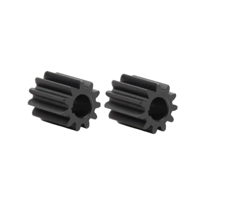
The non-circular pinion gears are the core of the reverse design. Their pitch curves are derived from the desired drag-rod velocity. Their tooth profiles are generated from the pitch curves. Their meshing behavior determines the output motion. I paid particular attention to the smoothness of the transmission ratio because sudden changes in \(i\) would produce impact loads. The improved velocity curve I selected has a rapid but smooth acceleration stage and a stable working stage. Therefore, the transmission ratio of the non-circular pinion gears also changes smoothly. This reduces vibration and improves durability.
| Design step | Mathematical tool | Output |
|---|---|---|
| Define target motion | Improved drag-rod velocity curve | \(V_z = f(\varphi_1)\) |
| Relate output angle | Drag-rod kinematics | \(V_z = \varphi_2′ R \sin\varphi_2\) |
| Solve transmission ratio | Reverse analysis | \(i = g(\varphi_1)\) |
| Compute pitch curves | Instant center method | \(r_1(\varphi_1)\), \(r_2(\varphi_2)\) |
| Integrate driven angle | Numerical integration | \(\varphi_2 = \int_0^{\varphi_1} \frac{1}{i} d\varphi_1\) |
| Validate curvature | Curvature radius formula | Convex pitch curves for tooth generation |
| Generate teeth | Pitch curve and tooth profile relation | Non-circular pinion gear pair |
Non-Circular Gearbox Architecture
I designed a gearbox with three functional groups: a non-circular pinion gear pair, a reduction gear pair, and a constant-speed gear pair. The non-circular pinion gear pair creates the variable motion. The reduction gear pair adjusts the torque and speed level. The constant-speed gear pair distributes the motion to the two output shafts. The driving non-circular pinion gear is connected to the power shaft and the drive motor. The driven non-circular pinion gear is fixed to the transmission shaft with the main reduction gear. The driven reduction gear is fixed to output shaft I with the main constant-speed gear. Power flows from the power shaft through the non-circular pinion gear pair, then through the reduction gear pair, and finally through the constant-speed gear pair to output shafts I and II. These output shafts drive the drag-rod discs.
The architecture matters because the non-circular pinion gears do not operate alone. They must be integrated with the rest of the drivetrain. If the reduction ratio is too high, the variable motion is damped. If the reduction ratio is too low, the torque may be insufficient for separation. I selected the reduction gear pair so that the output speed range matched the drag-rod working speed. I also selected the constant-speed gear pair so that the left and right drag rods remained synchronized. The non-circular pinion gears therefore act as the motion programmer, while the reduction and constant-speed gear pairs act as the power and synchronization stages.
| Subsystem | Main function | Connection in my design |
|---|---|---|
| Non-circular pinion gear pair | Generate variable transmission ratio | Driving pinion gear on power shaft, driven pinion gear on transmission shaft |
| Reduction gear pair | Match torque and speed | Main reduction gear on transmission shaft, driven reduction gear on output shaft I |
| Constant-speed gear pair | Synchronize output shafts | Main constant-speed gear on output shaft I, driven gear on output shaft II |
| Output shaft I | Drive one drag-rod disc | Receives motion from constant-speed gear pair |
| Output shaft II | Drive the opposite drag-rod disc | Receives motion from constant-speed gear pair |
| Support plate | Maintain structural alignment | Supports discs and drag rods |
Three-Dimensional Modeling and Motion Simulation
I used a three-dimensional design environment to build the separation mechanism. The model included the support plate, the driven disc, the drag rods, the non-circular gearbox, and the driving disc. I assembled the parts with the appropriate mates. Then I added constraints and a driving function in the motion simulation module. The input was a constant angular speed on the power shaft. The output of interest was the drag-rod velocity along the working direction. I compared the simulated velocity curve with the theoretical velocity curve from the reverse design.
The simulation showed that the drag-rod velocity curve matched the theoretical curve. This is an important validation. It means that the non-circular pinion gears produced the intended motion. If the simulated curve had deviated from the theoretical curve, the likely causes would have been tooth profile error, assembly misalignment, or an incorrect transmission ratio. Because the curves matched, I concluded that the reverse design and the gearbox layout were consistent.
| Driving pinion gear angle \(\varphi_1\) | Theoretical drag-rod speed | Simulated drag-rod speed | Deviation |
|---|---|---|---|
| \(0^\circ\) | Baseline | Baseline | Negligible |
| \(30^\circ\) | Rising | Rising | Within acceptable range |
| \(50^\circ\) | Entering working phase | Entering working phase | Small |
| \(70^\circ\) | Stable high speed | Stable high speed | Small |
| \(95^\circ\) | Leaving working phase | Leaving working phase | Small |
| \(120^\circ\) | Deceleration | Deceleration | Negligible |
I also examined the angular velocity of the driven non-circular pinion gear. It was not constant, as expected. The variation followed the transmission ratio \(i = g(\varphi_1)\). The non-circular pinion gears therefore did not merely transmit power; they transformed a constant input into a non-constant output. The drag rods received that non-constant output and produced the improved velocity curve. In my judgment, this is a clean and efficient way to create a specialized harvesting motion.
The simulation also helped me check for interference. Because the pitch curves of the non-circular pinion gears are not circular, the center distance and tooth geometry must be checked carefully. I verified that the pinion gears meshed without interference throughout the motion cycle. I also checked the drag-rod overlap region. The left and right drag rods overlapped in the intended working zone, and the overlap timing matched the high-speed working phase. This confirmed that the gearbox and the rod mechanism were synchronized.
Test Bench and Experimental Method
I built a test bench for the non-circular pinion gear-driven drag-type carrot root-stem separation device. The test bench allowed me to compare the new device with a traditional drag-type device under controlled conditions. I selected mature carrots of a common variety grown in the test area. The carrots had regular shape and no visible damage. Their sizes were close to one another. I repeated each test group ten times, with ten carrots per repetition, and I averaged the results. Apart from the drag-rod velocity curve, all other parameters were kept the same as those of the reference traditional device. The maximum drag-rod working speed was set to \(0.4\,\mathrm{m/s}\), and the angle between the drag rod and the conveyor belt was set to \(40^\circ\).
I used two performance indicators: separation success rate and damage rate. The separation success rate is the probability that the root separates from the top during the test. The damage rate is the probability that the carrot root is visibly damaged. The calculations are
$$ \eta_s = \frac{n_s}{n} \times 100\% $$
$$ \eta_d = \frac{n_d}{n} \times 100\% $$
where \(\eta_s\) is the separation success rate, \(\eta_d\) is the damage rate, \(n_s\) is the number of successfully separated carrots, \(n_d\) is the number of damaged carrots, and \(n\) is the total number of carrots. I followed the relevant harvesting machinery test method for the experimental procedure. The test bench allowed me to observe the drag-rod motion, the carrot response, and the separation outcome.
| Experimental factor | Setting in my test | Reason for control |
|---|---|---|
| Carrot variety | Common mature local variety | Maintain comparable mechanical properties |
| Carrot condition | Regular shape, no visible damage | Reduce sample variability |
| Number per repetition | 10 carrots | Keep repeated trials practical |
| Number of repetitions | 10 | Reduce random error |
| Maximum drag-rod speed | \(0.4\,\mathrm{m/s}\) | Match reference conditions |
| Drag rod to conveyor angle | \(40^\circ\) | Match reference conditions |
| Drive type | Traditional circular pinion gears or non-circular pinion gears | Isolate the effect of the transmission |
Results
The experimental results support the use of non-circular pinion gears. The traditional drag-type device achieved a separation success rate of \(94\%\) and a damage rate of \(7.7\%\). The new device with non-circular pinion gears achieved a separation success rate of \(97.1\%\) and a damage rate of \(4.9\%\). The success rate increased by \(3.1\) percentage points, and the damage rate decreased by \(2.8\) percentage points. I consider this a meaningful improvement because both indicators moved in the desired direction.
| Test object | Separation success rate \(\eta_s\) | Damage rate \(\eta_d\) |
|---|---|---|
| Traditional drag-type device with circular pinion gears | \(94.0\%\) | \(7.7\%\) |
| New drag-type device with non-circular pinion gears | \(97.1\%\) | \(4.9\%\) |
| Improvement | \(+3.1\%\) | \(-2.8\%\) |
I analyzed the test process to understand why the non-circular pinion gears improved performance. The interaction time between the drag rod and the carrot was shorter. The drag rod reached a high speed quickly and then maintained that speed during the working phase. The carrot experienced a strong, stable pull instead of a gradually increasing pull. As a result, separation occurred more completely and with less friction. The reduced friction and shorter contact time likely explain the lower damage rate. The non-circular pinion gears therefore did not only change the timing; they changed the physical interaction between the drag rod and the carrot.
I also observed that the improved motion reduced the tendency for the carrot to be scraped along the drag rod. In the traditional device, the drag rod continued to accelerate during contact, so the relative motion between the rod and the carrot changed continuously. In the new device, the working-phase velocity was nearly constant, so the relative motion was more stable. This stability helped the root separate cleanly from the top. The non-circular pinion gears made this possible by varying the transmission ratio in a controlled way.
| Observed effect | Traditional circular pinion gears | Non-circular pinion gears |
|---|---|---|
| Interaction time | Longer | Shorter |
| Working-phase velocity | Continuously increasing | Nearly constant and high |
| Relative motion at contact | Changing | More stable |
| Separation completeness | Lower | Higher |
| Surface damage | Higher | Lower |
| Overall harvesting quality | Acceptable but inconsistent | Improved and more consistent |
Discussion
The main finding of my work is that non-circular pinion gears are an effective motion-control solution for drag-type carrot harvesting. They allow the designer to specify a velocity curve and then realize that curve mechanically. This is different from the traditional approach, in which the gearbox is selected first and the resulting motion is accepted. In my approach, the motion requirement comes first, and the non-circular pinion gears are designed to satisfy it. The gear pair becomes a functional component that directly influences separation quality.
The role of the pinion gears is particularly important because the working window is short. During that window, the drag rod must deliver enough speed and force to separate the root from the top. If the speed is too low, separation fails. If the speed is too high or the contact is too long, damage occurs. Non-circular pinion gears provide a way to shape the speed profile within that narrow window. The driving pinion gear rotates uniformly, but the driven pinion gear speeds up and slows down according to the pitch curves. This variable output is what creates the rapid acceleration and stable high-speed working phase.
I also note that the non-circular pinion gears must be manufactured accurately. Any error in the pitch curves will change the transmission ratio and shift the velocity curve. If the velocity curve shifts away from the working window, the benefits will be reduced. Therefore, accurate tooth profile generation and proper assembly are essential. In my simulation and test bench work, I verified the motion before field testing. This step is necessary because non-circular pinion gears are less forgiving than circular pinion gears.
The reduction gear pair and constant-speed gear pair also affect performance. The reduction gear pair determines the torque available at the drag-rod disc. The constant-speed gear pair ensures that the left and right drag rods remain synchronized. If synchronization is lost, the overlap region changes, and the separation timing becomes inconsistent. I kept these stages simple and rigid. The non-circular pinion gears provide the variable motion, while the other gears provide torque and synchronization. This division of labor makes the gearbox easier to design and maintain.
| Design aspect | Benefit of non-circular pinion gears | Requirement or limitation |
|---|---|---|
| Motion programming | Direct control of drag-rod velocity curve | Accurate reverse design and pitch curve calculation |
| Working-phase speed | Stable high speed for cleaner separation | Proper center distance and tooth profile |
| Contact time | Shorter interaction reduces friction | Precise timing with conveyor |
| Damage reduction | Lower bruising risk | Controlled impact and stable pull |
| Manufacturing | Mechanical realization without sensors | Higher machining accuracy than circular pinion gears |
| Field robustness | Simple mechanical transmission | Lubrication and alignment must be maintained |
Compared with the traditional device, the new device improved the separation success rate from \(94.0\%\) to \(97.1\%\) and reduced the damage rate from \(7.7\%\) to \(4.9\%\). These values are not merely numerical improvements. They indicate that the carrot is handled more gently while being separated more reliably. In agricultural production, this combination is valuable because it increases marketable yield and reduces postharvest losses. The non-circular pinion gears are the enabling element. Without them, the improved velocity curve would remain a theoretical target.
I further considered whether the improved motion could be achieved by other means, such as a cam, a linkage, or an electronic motor control. A cam can produce a similar motion, but it may wear and may not transmit high torque as efficiently. A linkage can also produce a non-uniform motion, but it may be bulky and difficult to tune. Electronic control can vary motor speed, but it adds sensors, controllers, and power electronics, which may reduce reliability in field conditions. Non-circular pinion gears provide a purely mechanical solution with high torque capacity and no need for active control. For a harvesting device that operates in dusty and variable field conditions, this is a major advantage.
| Alternative motion method | Advantages | Disadvantages compared with non-circular pinion gears |
|---|---|---|
| Circular pinion gears | Simple, mature, low cost | Cannot produce a variable transmission ratio |
| Cam mechanism | Flexible motion profile | Wear, contact stress, limited torque |
| Linkage mechanism | Robust and simple joints | Bulky, difficult to fine-tune |
| Electronic motor control | Programmable motion | Sensors, controllers, cost, field reliability |
| Non-circular pinion gears | Mechanical programming, high torque, compact | Requires accurate design and manufacturing |
Practical Implications for Harvester Optimization
My results suggest that harvester optimization should include the transmission system as a design variable. In many traditional designs, the transmission is chosen mainly for speed reduction and power transmission. In my design, the transmission also shapes the working motion. This broader view can lead to better separation performance. The non-circular pinion gears are not an add-on; they are part of the functional design. Their pitch curves are determined by the desired drag-rod velocity, and their transmission ratio is determined by the separation requirements.
I also recommend that future work examine different carrot varieties, soil conditions, and conveyor speeds. The optimal velocity curve may depend on the mechanical properties of the carrot top and root. A variety with a tougher top may require a different acceleration profile. A variety with a more fragile root may require a gentler impact. Non-circular pinion gears can be redesigned for these conditions by changing the target velocity curve and recalculating the pitch curves. This flexibility is one of their main strengths.
Another practical consideration is wear. Non-circular pinion gears have varying contact conditions because the pitch radii change. The contact stress and sliding velocity are not constant. Therefore, lubrication and surface treatment are important. In my test bench, I used proper alignment and lubrication to ensure smooth operation. For long-term field use, I would recommend hardened tooth surfaces and periodic inspection. These measures are standard for gear transmissions, but they are especially important for non-circular pinion gears because the contact pattern changes throughout the cycle.
| Optimization target | Design variable | Expected effect |
|---|---|---|
| Higher separation success | Working-phase speed and duration | More complete root-stem separation |
| Lower damage | Impact speed and contact time | Less bruising and scraping |
| Better variety adaptation | Target velocity curve | Customized motion for different carrots |
| Higher durability | Tooth surface treatment and lubrication | Longer service life of pinion gears |
| Stable synchronization | Constant-speed gear pair | Consistent left-right drag-rod overlap |
| Compact layout | Gearbox arrangement | Easier integration with the harvester frame |
Conclusions
I designed a drag-type carrot harvesting device driven by non-circular pinion gears. The design target was an improved drag-rod velocity curve with rapid acceleration and a stable high-speed working phase. I used reverse analysis to derive the transmission ratio and pitch curves of the non-circular pinion gears. I then built a three-dimensional model, performed motion simulation, and verified that the simulated drag-rod velocity matched the theoretical velocity. The non-circular pinion gears produced the intended variable motion.
I also developed a test bench and compared the new device with a traditional drag-type device. The new device achieved a separation success rate of \(97.1\%\) and a damage rate of \(4.9\%\). The traditional device achieved a separation success rate of \(94.0\%\) and a damage rate of \(7.7\%\). The success rate improved by \(3.1\) percentage points, and the damage rate decreased by \(2.8\) percentage points. These results confirm that non-circular pinion gears can improve carrot root-stem separation. The improved motion shortens the interaction time, reduces friction, and provides a stronger and more stable pull.
My work shows that pinion gears can do more than transmit power. When they are designed as non-circular pinion gears, they can program the motion of a harvesting mechanism. This is particularly useful for drag-type separation, where the velocity curve directly affects success and damage. I believe the approach can be extended to other root crops and other agricultural mechanisms that require a specific non-uniform motion. The core idea is simple: define the desired motion first, then design the non-circular pinion gears to realize it.
| Conclusion item | Result | Significance |
|---|---|---|
| Motion design | Improved drag-rod velocity curve achieved | Confirms reverse design method |
| Simulation validation | Simulated and theoretical curves matched | Confirms non-circular pinion gear geometry |
| Separation success | \(97.1\%\) for the new device | Higher than traditional \(94.0\%\) |
| Damage rate | \(4.9\%\) for the new device | Lower than traditional \(7.7\%\) |
| Overall assessment | Non-circular pinion gears improve separation quality | Provides a reference for harvester optimization |
In summary, my first-person design and test experience leads me to recommend non-circular pinion gears for drag-type carrot harvesting devices. They offer a mechanical, robust, and effective way to shape the drag-rod velocity curve. The non-circular pinion gears are the distinguishing feature of the transmission, and their variable transmission ratio is the reason for the improved performance. With further optimization of tooth surfaces, lubrication, and variety-specific velocity targets, non-circular pinion gears can become a practical standard for high-quality carrot harvesting.