
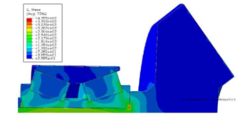
The equivalent stress distribution of the gear assembly and the gear shaft is shown. It can be seen from the figure that the maximum stress occurs at the bottom of the shoulder, and the stress at the top of the shoulder is less than the stress at the bottom. This is to simplify the calculation and change the chamfering of the bottom of the shoulder and the inner ring of the bearing into a right angle, resulting in the stress concentration at the bottom of the shoulder.
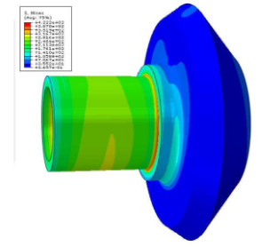
From the deformation of gear assembly, the fretting condition of gear shoulder and bearing surface can be analyzed. In the repeated cyclic meshing of the gear, the matching unit between the shoulder and the bearing produces continuous deformation difference and dislocation, resulting in the fretting of the matching surface between the shoulder and the bearing.
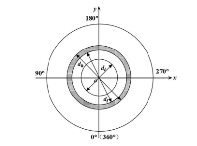
In order to analyze the change rule of the gear shaft shoulder micro movement, the polar coordinates as shown in the figure are established, and the bottom corresponding to the meshing point on the gear shaft is defined as the polar angle 0 °, and the position of the meshing point is defined as the polar angle 180 °. In Figure 3, Di is the diameter of the inner ring of the gear shaft, DL is the diameter of the circle at the bottom of the shoulder, and DH is the diameter of the circle at the top of the shoulder. If the total height of the gear shaft shoulder is set to L, then l = (DH DL) / 2. If the height of a point on the gear shaft shoulder is set to L, the relative height of this point can be expressed in L / L. In order to better analyze the stress and strain distribution of the shoulder, the equal spacing of the shoulder is divided into grids, and the positions of 25%, 50%, 75% and 100% of the shoulder height L (i.e. the relative height of the shoulder L / L = 0.25, 0.5, 0.75 and 1) are taken for analysis
(1) The change law of contact stress σ C
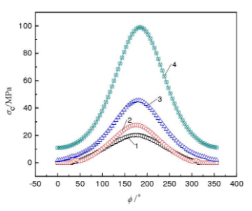
During the operation of the gear shaft, the stress of each node of the gear shoulder changes with the change of the meshing force of the gear. The change rule of contact stress of gear shaft shoulder is shown in the figure. Because there are grooves at the bottom of the actual gear shoulder, and the bottom of the gear shoulder of the simulation model is simplified into a right angle, resulting in the stress concentration effect at the bottom of the gear shoulder, so the stress change at the bottom of the shoulder is not considered in the simulation results analysis. It can be seen from the figure that the contact stress of the gear shaft shoulder (represented by σ C) is generally increasing from the bottom to the top of the shaft shoulder, and the contact stress is parabola distribution at the polar angle ⌀ = 180 ° (gear engagement position). The contact stress increases from 0.93mpa to 20.2mpa in the circumference with shoulder height of 0.25 and from 11mpa to 99mpa in the circumference with shoulder height of L. That is to say, when the polar angle is fixed, the contact stress increases with the increase of shoulder height.
(2) The change rule of axial deformation τ x
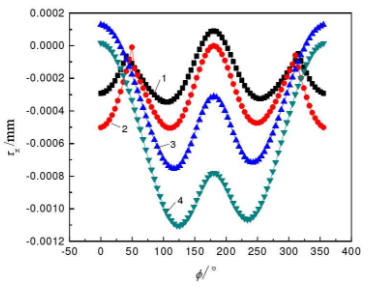
The change rule of the axial deformation of the gear shoulder (represented by τ x) is shown in the figure: the axial deformation is symmetrically distributed at the position of the polar angle = 180 °; when the polar angle is fixed, the axial deformation increases with the increase of the shoulder height. When the relative height of the shaft shoulder is 0.25, the axial deformation reaches the maximum value of 0.00035mm at the polar angle ⌀ = 103.5 ° and ⌀ = 256.5 °; when the relative height of the gear shaft shoulder is L / L = 1, the axial deformation reaches the maximum value of 0.0011mm at the polar angle ⌀ = 126 ° and ⌀ = 234 °. The negative value of axial deformation indicates that the movement direction of the shoulder is opposite to the axial direction set by the model. When the relative height L / L of the shoulder is 0.5 and 0.75, the axial deformation appears positive value, which indicates that the axial deformation of the shoulder changes with the time and position during the operation of the gear shaft.
(3) The change law of radial deformation τ y
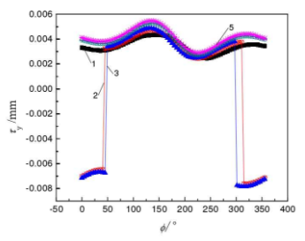
The change rule of the radial deformation of the gear shoulder (represented by τ y) is shown in Fig. 2.12: the radial deformation generally presents a wave linear distribution within the polar angle = 0 ° to = 360 °; in the case of a certain polar angle, the radial deformation generally increases with the increase of the shoulder height.
When the relative height L / L of the shoulder is 0.25 and 0.5, the radial deformation is negative, indicating that the movement direction of the shoulder is opposite to the radial direction set by the model. Among them, when the relative height L / L of the shoulder is 0.25, the radial deformation changes from – 0.0076mm to – 0.0065mm within the range of – 45 ° ~ 40.5 °; when the relative height L / L of the shoulder is 0.5, the radial deformation changes from – 0.0078mm to – 0.0067mm within the range of – 58.5 ° ~ 45 °. When the shoulder height is 0, the radial deformation changes from 0.0025mm to 0.0043mm. When the shoulder height is l, the radial deformation changes from 0.0029mm to 0.005mm.
In conclusion, the axial and radial deformation of the gear shoulder is caused by the bending deformation of the gear shaft caused by the meshing force of the gear. During the operation of the gear shaft, the deformation of the node on the circumference of the gear shaft shoulder can be understood as the deformation of a node at different circumferential positions during the operation. The above simulation results show that the axial and radial deformation of the shoulder surface changes with the time and position during the operation of the gear shaft.