1.Finite element modeling of helical gear
The basic idea of establishing carburized helical gear under ANSYS is to first establish fitting involute according to involute equation, and then construct the entire end tooth profile by combining the tooth top circle, tooth root circle and tooth root transition curve. Finally, helical scan the generated end tooth profile along the tooth width direction to obtain the helical gear entity. When establishing the fitting involute, the fitting should be based on the calculated points on the involute, because ANSYS does not provide a direct tool for generating mathematical curves. By controlling the number of points on the fitting involute, the accuracy of the generated involute spiral surface can be adjusted conveniently. At the same time, the mesh is refined.
The known gear parameters are: number of teeth Z1 = 18, Z2 = 31, modulus M = 8, helix angle β = 14 ° 26’43 “, tooth width B1 = 100 mm, B2 = 95 mm. The big gear is right-handed and the small gear is left-handed. The elastic modulus of carburized gear material is 2.17 × 10⁵Mpa, Poisson’s ratio is 0.28, density is 7850 kg · m-3.
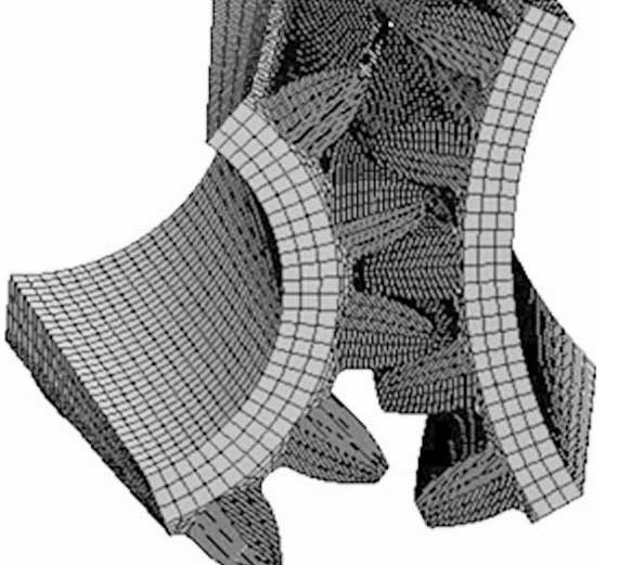
In order to carry out contact fatigue analysis, a simplified five tooth pair model is used in the establishment of the finite element model of helical gear. At the same time, different densities are used for different parts of the gear teeth when meshing, and the smoothness of mesh transition in different parts is also considered. The purpose of doing this is to improve the efficiency of calculation, and at the same time, to meet the requirements of calculation accuracy and calculation economy. When the helical gear is assembled, the initial position is the pitch circle engagement position of the third tooth, and the final finite element mesh model of the helical gear pair is as shown in the figure.

2.Contact fatigue analysis of carburized gear
The fatigue analysis of awe fatigue module is based on the results of linear static analysis. For the application of load and constraint in contact fatigue analysis of helical gear, please refer to the static analysis for setting. Firstly, the contact pairs are established between the assembly of the helical gear pair. The upper surface of all the teeth of the driving wheel is selected as the contact surface, and the lower surface of all the teeth of the driven wheel is selected as the target surface. At the same time, a fixed constraint is applied to the inner ring surface of the driven wheel to limit all the degrees of freedom, and a driving torque is applied to the driving wheel to set its size as 2046.4 n · M. The service life of the helical gear pair is set as 3 × 10⁷ times. After the awe fatigue module fatigue calculation, the contact fatigue life of the helical gear pair can be obtained. The results show that there is no contact fatigue failure in the set life range.

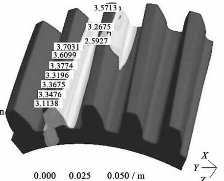
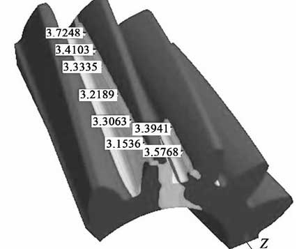
In order to analyze the fatigue damage of the tooth surface of carburized helical gear, the safety factor of the fatigue calculation results is shown, and the contact fatigue safety factor nephogram of the driving wheel and the driven wheel are obtained respectively, as shown in Fig. 2 and Fig. 3. It can be seen from the figure that the contact fatigue safety factor of the driving wheel is between 3 and 4, the safety factor of the driven wheel is between 2.5 and 4, and the minimum safety factor appears near the tooth top of the contact line, all of which exceed 2.
Through the contact fatigue analysis of carburized helical gear, it can be seen that the contact fatigue of carburized and quenched gear meets the use requirements, with high safety factor and good performance.

As a widely used mechanical transmission part, it is of great significance to improve the service life of gears. Carburizing and quenching treatment is one of the ways to improve the wear resistance and hardness of gears. This paper analyzes the current situation of gear heat treatment, discusses the improvement methods, and puts forward the gear carburizing and quenching process flow of carburizing, precooling quenching, high temperature tempering, secondary quenching and low temperature tempering. On this basis, the finite element model of contact analysis of helical gear after carburizing and quenching is established, and the contact fatigue life analysis is carried out under awe fatigue module, and the contact fatigue life and contact fatigue safety coefficient are obtained. The analysis results show that the carburizing and quenching process proposed in this paper can significantly improve the performance of helical gear, and its life meets the requirements, It also provides a basis for further optimization of gears. At the same time, the finite element contact fatigue simulation results of the gear provide a reference for the durability test of the physical prototype.
