
In my study of carburizing quenching for helical gears, I focused on a high-performance 9310 aviation steel commonly used for heavily loaded transmission components. Helical gears are among the most important power-transmission elements in automotive, marine, engineering machinery, and aerospace systems. Their tooth surfaces are inclined helicoids, which allows smoother meshing, higher contact ratio, and lower dynamic load than spur gears. However, the same geometry that improves transmission behavior also makes heat-treatment simulation more complex. The carburizing quenching process introduces coupled temperature, carbon diffusion, phase transformation, stress, strain, and hardness fields. My objective was to build a numerical framework that can link these fields for helical gears and then use that framework to evaluate how selected process parameters influence final gear performance.
I approached the problem in four stages. First, I created a parameterized geometric model of an involute cylindrical helical gear. Second, I calculated and organized the thermophysical properties of 9310 steel, including phase-transformation kinetics, diffusion behavior, thermal properties, and flow stress. Third, I established a multi-physics finite-element model for a two-dimensional single-tooth cross-section of a helical gear. Fourth, I performed a series of numerical experiments by changing ambient carbon concentration, diffusion-stage carburizing time, and quenching-oil temperature. The results provide a practical basis for selecting carburizing quenching parameters for helical gears.
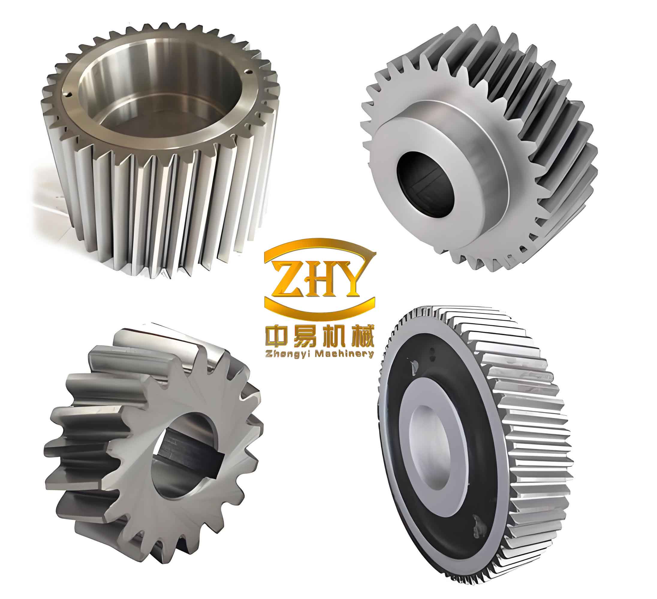
1. Parametric Geometric Modeling of Helical Gears
The accuracy of any carburizing quenching simulation for helical gears depends strongly on the geometric model. If the tooth profile, root transition, or helical surface is approximated too roughly, the carbon diffusion path, heat-transfer area, stress concentration, and hardness gradient will all be affected. Therefore, I used a parametric approach rather than a fixed one-off model. In this approach, the main dimensions of the helical gears can be updated by changing a small set of input parameters.
For involute cylindrical helical gears, the end-face profile is an involute curve, and the tooth surface is generated by sweeping that profile along a helical line. In industrial production, helical gears are often manufactured by hobbing or gear shaping. Hobbing can be understood as a continuous generating process in which a hob and the gear blank rotate in a crossed-axis relationship. The hob mimics a rack cutter, and the tooth space is progressively cut by the relative motion. Gear shaping uses a pinion-shaped cutter and a reciprocating motion. Both processes are based on conjugate tooth-surface generation. I used these principles to derive the basic equations needed for modeling.
1.1 Involute and Transition Equations
The involute curve forms the working part of the tooth flank. For a base radius \(r_b\) and a pressure angle \(\alpha_k\) at a point on the involute, I used the following polar relations:
$$
r_k=\frac{r_b}{\cos\alpha_k}
$$
$$
\theta_k=\tan\alpha_k-\alpha_k
$$
For direct use in a three-dimensional CAD environment, I converted the involute into Cartesian coordinates:
$$
\begin{aligned}
x &= r_b(\cos t+t\sin t)\\
y &= r_b(\sin t-t\cos t)
\end{aligned}
$$
The root transition curve is also important because it controls stress concentration in helical gears. I represented the transition curve generated by a rack-type cutter with a dual-radius tip. The main parametric form can be written as:
$$
\begin{aligned}
x &= r_p\sin\phi-(a-l)\cos(\phi-\alpha’)\\
y &= r_p\cos\phi+(a-l)\sin(\phi-\alpha’)
\end{aligned}
$$
where \(r_p\) is the cutter tip radius, \(a\) is the distance from the center of the cutter tip arc to the centerline, \(l\) is the horizontal offset, and \(\alpha’\) is an angular parameter. The relation between \(\phi\) and \(\alpha’\) can be expressed as:
$$
\phi=\frac{a+l\cot\alpha’}{r_p}
$$
This transition representation allowed me to avoid replacing the root fillet with a simple circular arc. As a result, the finite-element model preserved a more realistic root geometry for helical gears.
1.2 Helical Tooth Surface Equation
A helical tooth surface can be obtained by rotating the end-face profile while translating it along the gear axis. If the end-face profile is given by \(x(u)\), \(y(u)\), and the helical parameter is \(p\), I wrote the tooth surface as:
$$
\mathbf{R}(u,\theta)=
\begin{bmatrix}
x(u)\cos\theta-y(u)\sin\theta\\
x(u)\sin\theta+y(u)\cos\theta\\
p\theta
\end{bmatrix}
$$
For a reference radius \(r\) and helix angle \(\beta\), the helical parameter is:
$$
p=\frac{r}{\tan\beta}
$$
I used a positive helix angle for right-hand helical gears and a negative value for left-hand helical gears. This convention allowed the same parametric model to represent either hand of helical gears.
1.3 Parametric Modeling Workflow
I built the helical gear model in a CAD environment using equation-driven curves. The main workflow was as follows:
- Define the basic geometric parameters, including number of teeth, normal module, pressure angle, helix angle, addendum coefficient, and clearance coefficient.
- Calculate the transverse module, pitch diameter, base diameter, tip diameter, root diameter, and related radii.
- Draw the base circle, pitch circle, tip circle, and root circle on a sketch plane.
- Generate the involute curve using the Cartesian parametric equations.
- Generate the helical path using a three-dimensional equation-driven curve.
- Create a single tooth-space cut and apply the transition fillet.
- Pattern the cut around the gear axis to form the complete helical gears.
The main modeling parameters and expressions I used are summarized in Table 1.
| Parameter | Symbol | Expression |
|---|---|---|
| Number of teeth | \(z\) | Input |
| Normal module | \(m_n\) | Input |
| Pressure angle | \(\alpha\) | Input |
| Helix angle | \(\beta\) | Input |
| Addendum coefficient | \(h_a^*\) | Input |
| Clearance coefficient | \(c^*\) | Input |
| Transverse module | \(m_t\) | \(m_t=m_n/\cos\beta\) |
| Pitch diameter | \(d\) | \(d=m_t z\) |
| Base diameter | \(d_b\) | \(d_b=d\cos\alpha\) |
| Tip diameter | \(d_a\) | \(d_a=d+2h_a\) |
| Root diameter | \(d_f\) | \(d_f=d-2h_f\) |
| Helical parameter | \(p\) | \(p=r/\tan\beta\) |
The resulting model is a parameterized involute cylindrical helical gear. I can modify the module, tooth number, helix angle, or pressure angle and regenerate the geometry without rebuilding every curve manually. This is especially useful when several process simulations must be compared for helical gears with different designs.
2. Thermophysical Property Model for 9310 Steel
Carburizing quenching is not only a thermal process. It is a diffusion-controlled surface-hardening process followed by a rapid cooling process that drives austenite-to-martensite transformation. For helical gears, the final hardness, residual stress, and distortion depend on the interaction between carbon concentration, temperature history, phase transformation, and mechanical restraint. I therefore built a thermophysical property model for 9310 steel before running the finite-element simulations.
2.1 Carburizing Principle
During carburizing, helical gears are placed in a carbon-rich atmosphere at a temperature in the austenite region, typically between 880°C and 950°C. Carbon atoms diffuse from the surface into the interior because of the concentration gradient. The surface carbon concentration approaches the furnace carbon potential, while the core remains close to the original low-carbon composition. After carburizing, the surface layer behaves like high-carbon steel, whereas the core retains low-carbon toughness. This combination is desirable for helical gears because the surface must resist wear and contact fatigue while the core must resist bending fatigue and impact.
I treated the carbon diffusion process using Fick’s second law. For a general three-dimensional case:
$$
\frac{\partial C}{\partial t}=
D\left(
\frac{\partial^2 C}{\partial x^2}+
\frac{\partial^2 C}{\partial y^2}+
\frac{\partial^2 C}{\partial z^2}
\right)
$$
For a one-dimensional approximation through the tooth depth, this reduces to:
$$
\frac{\partial C}{\partial t}=D\frac{\partial^2 C}{\partial x^2}
$$
The initial condition is:
$$
C(x,0)=C_0
$$
The surface boundary condition with a finite mass-transfer coefficient is:
$$
-D\left.\frac{\partial C}{\partial x}\right|_{x=0}
=\beta(C_p-C_s)
$$
where \(C_0\) is the initial carbon concentration, \(C_p\) is the furnace carbon potential, \(C_s\) is the surface carbon concentration, and \(\beta\) is the interface mass-transfer coefficient. The diffusion coefficient and mass-transfer coefficient follow Arrhenius-type relations:
$$
D=D_0\exp\left(-\frac{Q_D}{RT}\right)
$$
$$
\beta=\beta_0\exp\left(-\frac{Q_\beta}{RT}\right)
$$
For the material model I used \(D_0=0.162\ \text{cm}^2/\text{s}\), \(Q_D=137800\ \text{J/mol}\), \(\beta_0=4.37\times 10^{-2}\ \text{m/s}\), and \(Q_\beta=79953\ \text{J/mol}\). The corresponding analytical solution for a semi-infinite medium with surface mass transfer can be written as:
$$
C(x,t)=C_0+(C_p-C_0)
\left[
\operatorname{erfc}\left(\frac{x}{2\sqrt{Dt}}\right)
-\exp\left(\frac{\beta x}{D}+\frac{\beta^2 t}{D}\right)
\operatorname{erfc}\left(\frac{x}{2\sqrt{Dt}}+\beta\sqrt{\frac{t}{D}}\right)
\right]
$$
This solution helped me interpret the numerical carbon profiles obtained from the finite-element model. In helical gears, the carbon profile is not perfectly one-dimensional because of tooth curvature and root geometry, but the analytical form is still useful for checking the order of magnitude and the expected diffusion depth.
2.2 Quenching and Phase Transformation
After carburizing, helical gears are quenched to transform austenite into martensite. The cooling rate must exceed the critical cooling rate of the steel in the regions where hardening is required. The transformation depends on temperature, carbon content, alloy composition, and stress state. I described the austenite-to-martensite transformation using a Koistinen-Marburger-type relation:
$$
\zeta_M=1-\exp[-\alpha(M_s-T)]
$$
where \(\zeta_M\) is the martensite volume fraction, \(M_s\) is the martensite start temperature, \(T\) is the current temperature, and \(\alpha\) is a material constant. For a more general description including carbon and stress effects, I used a Function-type relation:
$$
\zeta_M=
1-\exp\left[
-\psi_1(T)
\left(
1-\exp\left(\psi_2(C-C_0)+\psi_{31}\sigma_m+\psi_{32}\bar{\sigma}+\psi_4\right)
\right)
\right]
$$
Here, \(C\) is the local carbon concentration, \(C_0\) is the initial carbon concentration, \(\sigma_m\) is the mean stress, \(\bar{\sigma}\) is the equivalent stress, and \(\psi_1\), \(\psi_2\), \(\psi_{31}\), \(\psi_{32}\), and \(\psi_4\) are coefficients. In my baseline simulations, external stress was zero before quenching, so the stress terms did not dominate the initial transformation. However, they become important when residual stress and transformation plasticity are coupled.
For diffusion-controlled transformations, I used an Avrami-type kinetic equation:
$$
f_a=
1-\exp\left[
-\left(
k_0 t\exp\left(-\frac{Q}{RT}\right)
\right)^n
\right]
$$
where \(f_a\) is the transformed fraction, \(t\) is time, \(R\) is the gas constant, and \(k_0\), \(Q\), and \(n\) are material parameters. This form is convenient for finite-element implementation because it relates isothermal holding time to transformed volume fraction.
2.3 Thermal and Mechanical Properties
I calculated the temperature-dependent properties of 9310 steel using a material-property simulation tool. Because 9310 steel contains multiple phases, the effective property at a given temperature was obtained by a mixture rule:
$$
P=\sum_i x_i P_i+\sum_i\sum_{j>i}x_i x_j\Omega_{ij}(x_i-x_j)
$$
where \(x_i\) is the mass fraction of phase \(i\), \(P_i\) is the property of phase \(i\), and \(\Omega_{ij}\) is an interaction term. I used this approach to estimate density, Young’s modulus, Poisson’s ratio, specific heat capacity, thermal conductivity, and thermal expansion coefficient. These properties were then imported into the finite-element model as temperature-dependent functions.
The chemical composition range of 9310 steel that I used is shown in Table 2.
| Element | C | Ni | Mn | Mo | Si | P | Cr | S |
|---|---|---|---|---|---|---|---|---|
| Content (wt.%) | 0.08–0.13 | 3.00–3.35 | 0.45–0.65 | 0.08–0.15 | 0.20–0.35 | ≤0.025 | 1.00–1.40 | ≤0.025 |
I also used critical transformation temperatures to define the phase-change windows. The approximate values from the material model are listed in Table 3.
| Transformation | Ferrite | Pearlite | Bainite | Martensite |
|---|---|---|---|---|
| Start temperature (°C) | 763.2 | 687.3 | 550.1 | 382.2 |
For the flow behavior of 9310 steel, I analyzed true stress–strain curves over a temperature range of 0°C to 400°C and strain rates of 0.001, 0.1, 1, and 100 s\(^{-1}\). The general trend was that flow stress decreases as temperature increases and increases as strain rate increases. At a fixed strain rate, the flow stress rises quickly at small strain, approaches a peak, and then evolves more gradually. At a fixed temperature, higher strain rate produces higher flow stress. I represented the flow stress using:
$$
\sigma=Y(T,C)+H(T,C)\bar{\varepsilon}
$$
where \(Y\) is the yield strength, \(H\) is the hardening modulus, and \(\bar{\varepsilon}\) is the equivalent strain. This relation was used in the mechanical part of the coupled model.
3. Multi-Physics Finite-Element Model for Helical Gears
I modeled the carburizing quenching of helical gears as a coupled multi-physics problem. The main fields were temperature, carbon concentration, phase fraction, stress, strain, and hardness. These fields interact continuously. For example, temperature controls diffusion and phase transformation; phase transformation releases latent heat and changes specific volume; stress affects transformation plasticity; and carbon concentration changes the martensite start temperature and hardness. The coupling relationships I considered are summarized in Table 4.
| Field | Primary variables | Main couplings |
|---|---|---|
| Temperature field | \(T(x,y,t)\) | Diffusion, phase transformation, thermal strain, heat transfer |
| Carbon field | \(C(x,y,t)\) | Phase kinetics, hardness, martensite start temperature |
| Microstructure field | \(f_a\), \(f_M\), \(f_{RA}\) | Latent heat, transformation strain, hardness |
| Stress–strain field | \(\sigma_{ij}\), \(\varepsilon_{ij}\) | Thermal strain, transformation plasticity, phase strain |
| Hardness field | \(H_e\) | Phase fractions, carbon content |
3.1 Temperature Field
For the temperature field, I solved the transient heat-conduction equation with a source term for latent heat and plastic dissipation:
$$
\rho c_p\frac{\partial T}{\partial t}
=
\lambda\left(
\frac{\partial^2 T}{\partial r^2}
+\frac{1}{r}\frac{\partial T}{\partial r}
+\frac{\partial^2 T}{\partial x^2}
\right)
+Q
$$
where \(\rho\) is density, \(c_p\) is specific heat capacity, \(\lambda\) is thermal conductivity, and \(Q\) is the heat source associated with phase transformation and deformation. I used an equivalent heat-capacity method to include latent heat:
$$
c_{\text{eff}}=c_p-\frac{L\Delta V}{\Delta T}
$$
where \(L\) is latent heat, \(\Delta V\) is the volume fraction change during a time step, and \(\Delta T\) is the temperature change during that step. The boundary condition between the helical gears and the surrounding medium was a convection condition:
$$
-\lambda\frac{\partial T}{\partial n}=h(T_w-T_f)
$$
where \(h\) is the surface heat-transfer coefficient, \(T_w\) is the workpiece surface temperature, and \(T_f\) is the medium temperature. For quenching, I used a temperature-dependent heat-transfer coefficient for the quenching oil. This coefficient strongly affects the cooling rate and therefore the martensite fraction.
3.2 Microstructure Field
For the microstructure field, I tracked the austenite, martensite, and retained austenite fractions. The baseline simulation considered the transformation from austenite to martensite. Because the surface carbon concentration is high in carburized helical gears, the martensite start temperature in the surface layer is lower than in the core. As a result, a thin surface layer may contain more retained austenite after quenching. The core, with lower carbon content, transforms more completely to martensite. This behavior is important for hardness prediction because retained austenite is softer than martensite.
I used the following relation for the transformed fraction during continuous cooling:
$$
\zeta_M=1-\exp[-\alpha(M_s-T)]
$$
The martensite start temperature was adjusted locally according to carbon content. The retained austenite fraction was then calculated as the remaining austenite that did not transform.
3.3 Stress–Strain Field
The total strain increment in the carburizing quenching process includes elastic, plastic, thermal, transformation, and transformation-plasticity contributions:
$$
d\varepsilon=d\varepsilon_e+d\varepsilon_p+d\varepsilon_{th}+d\varepsilon_{tr}+d\varepsilon_{tp}
$$
The elastic strain increment follows Hooke’s law:
$$
d\varepsilon_{ij}^e=
\frac{1+\nu}{E}d\sigma_{ij}
-\frac{\nu}{E}d\sigma_{kk}\delta_{ij}
$$
The plastic strain increment was described using a classical plasticity relation:
$$
d\varepsilon_{ij}^p=
\frac{3}{2}\frac{d\sigma_i}{H}\frac{\sigma_{ij}}{\sigma_i}
$$
The thermal strain increment was calculated from the phase-weighted thermal expansion coefficients:
$$
d\varepsilon_{th}=\sum_{k=1}^{5}m_k\alpha_k dT
$$
The transformation strain increment was calculated from the volume change associated with phase transformation:
$$
d\varepsilon_{tr}=\sum_{k=1}^{5}\beta_k^T dV_k
$$
I also included transformation plasticity:
$$
d\varepsilon_{ij}^{tp}=\frac{3}{2}K_{ij}(1-V)dV\,\sigma_{ij}
$$
where \(K_{ij}\) is the transformation-plasticity parameter, \(V\) is the volume fraction of the transforming phase, and \(dV\) is its increment. These terms are essential for predicting residual stress and distortion in helical gears.
3.4 Hardness Field
I predicted hardness using the volume-fraction method. The effective hardness of each element was calculated as a weighted average of the hardness of its constituent phases:
$$
H_e=\sum_i V_{fi}H_i
$$
For martensite, I used an empirical relation of the form:
$$
HV_M=
127+949C+27Si+11Mn+8Ni+16Cr+21\log V
$$
where \(C\), \(Si\), \(Mn\), \(Ni\), and \(Cr\) are alloying element contents and \(V\) is a cooling-rate parameter. For retained austenite, I used a correction relation:
$$
HRC_{RA}=\frac{1-0.2V_{RA}}{1+V_{RA}}
$$
This allowed me to evaluate the hardness gradient from the carburized surface to the core of the helical gears. The hardness result was not an independent input; it was derived from the predicted carbon profile and phase fractions.
3.5 Geometry, Mesh, and Boundary Conditions
A complete helical gear can be regarded as a single tooth repeated around the axis. To reduce computational cost while preserving the essential physical behavior, I extracted a two-dimensional single-tooth cross-section. This simplification is appropriate for studying carbon diffusion, phase transformation, stress evolution, and hardness distribution through the tooth depth. It also makes it practical to run multiple parameter cases for helical gears.
The steps I followed were:
- Import the two-dimensional tooth section into the finite-element environment.
- Convert the imported boundary segments into composite curves.
- Convert the closed curve set into a solid domain.
- Define the material properties as temperature- and carbon-dependent functions.
- Set the initial carbon concentration and initial temperature.
- Apply carbon-flux and heat-flux boundary conditions on the exposed tooth surface.
- Apply symmetry and zero-carbon-flux conditions on the cut boundaries.
- Generate a free quadrilateral mesh with refinement near the tooth surface.
The mesh I used had an average element quality of about 0.67 and approximately 7,882 elements. The surface region was refined more than the interior because the carbon gradient, phase gradient, and hardness gradient are steepest near the surface. Table 5 lists the baseline process parameters for the initial simulation.
| Parameter | Baseline value |
|---|---|
| Initial carbon concentration | 0.20 wt.% |
| Furnace carbon potential | 0.75 wt.% |
| Carburizing temperature | 900°C |
| Carburizing time | 8 h |
| Quenching-oil temperature | 80°C |
| Quenching time | 15 min |
| Considered phases | Austenite, martensite, retained austenite |
4. Baseline Simulation Results for Helical Gears
After solving the coupled model, I obtained the carbon concentration, phase distribution, stress–strain distribution, and hardness gradient for the helical gears. These results established the reference behavior for the subsequent parameter analysis.
4.1 Carbon Concentration
The carbon concentration was highest at the tooth surface and decreased toward the core. In the baseline case, the surface carbon concentration reached about 0.74 wt.%, while the core remained near 0.21 wt.%. The overall carbon range was approximately 0.20–0.74 wt.%. The profile was relatively smooth, which indicates that the diffusion stage was sufficient to avoid an excessively steep carbon gradient. For helical gears, a smooth carbon gradient is desirable because it reduces the risk of abrupt hardness change and excessive residual stress at the case-core interface.
4.2 Microstructure Distribution
The microstructure after quenching was dominated by martensite. The average austenite fraction was about 1.95%, and the average martensite fraction was about 98.1%. Near the surface, the austenite fraction reached about 31.9% in a very thin layer, while martensite was about 68.1%. The reason is that the high surface carbon content lowers the martensite start temperature, so some austenite remains untransformed as retained austenite. Moving toward the transition zone and the core, the carbon content decreases, the martensite start temperature increases, and the microstructure becomes almost fully martensitic. This spatial distribution is typical for carburized and quenched helical gears.
4.3 Stress and Strain
The quenching step produced large temperature gradients between the surface and the core. Because thermal contraction and phase transformation occur non-uniformly, the helical gears developed significant thermal stress and transformation stress. In the baseline result, the surface was in compression, while the core was in tension. The core stress was larger in magnitude than the surface stress. The strain rate decreased from the outer contour toward the inner contour. These results are consistent with the expected behavior of carburized quenching: the surface undergoes rapid cooling and martensitic expansion, while the core cools more slowly and constrains the surface layer.
4.4 Hardness Gradient
The hardness was highest at the tooth surface and decreased toward the core. The shape of the hardness curve followed the carbon concentration and martensite fraction curves. Because the surface layer had both higher carbon content and a high martensite fraction, it exhibited the greatest hardness. The transition zone showed a gradual decrease, and the core reached the lowest hardness. This gradient is important for helical gears because it combines wear resistance at the surface with toughness in the core.
5. Influence of Carburizing Quenching Parameters on Helical Gear Performance
After validating the baseline model, I performed a parametric study. I used a single-variable approach so that each process parameter could be evaluated independently. The parameters were ambient carbon concentration, diffusion-stage carburizing time, and quenching-oil temperature. The goal was to identify how each parameter affects carbon profile, phase fraction, stress, and hardness in helical gears.
5.1 Effect of Ambient Carbon Concentration
The ambient carbon concentration controls the surface carbon potential during diffusion. For a given carburizing time, a higher ambient carbon concentration increases the driving force for carbon diffusion into the helical gears. I designed four cases with carbon concentrations of 0.7, 0.8, 0.9, and 1.0 wt.%. The parameter groups are listed in Table 6.
| Group | Ambient carbon concentration (wt.%) |
|---|---|
| 1 | 0.70 |
| 2 | 0.80 |
| 3 | 0.90 |
| 4 | 1.00 |
The results showed that as the ambient carbon concentration increased, the surface carbon content of the helical gears increased. The carburized case depth also increased slightly. The core carbon content changed only slightly and remained close to the initial value of 0.20 wt.%. This means that the ambient carbon concentration mainly affects the surface layer, not the core. In practice, this is favorable because the core can retain toughness while the surface gains hardness and wear resistance.
The martensite distribution also changed with ambient carbon concentration. The core martensite fraction was almost unchanged, but the surface martensite fraction was sensitive to carbon concentration. When the surface carbon content was higher, the martensite start temperature decreased, so more austenite was retained after quenching. As a result, the surface martensite fraction decreased slightly even though the carbon content increased. The transition zone and core showed little change.
The hardness gradient followed the same trend as the carbon and martensite distributions. Higher ambient carbon concentration produced a slightly higher surface hardness. The difference was most visible near the surface and diminished toward the core. When the depth exceeded about 0.5 mm, the hardness curves for different carbon concentrations converged. This indicates that the ambient carbon concentration is a strong tool for controlling the surface hardness of helical gears, but it has limited influence on the core hardness.
5.2 Effect of Diffusion-Stage Carburizing Time
The diffusion-stage carburizing time controls how far carbon can diffuse into the helical gears. I selected four cases with carburizing times of 9, 10, 11, and 12 h. The parameter groups are listed in Table 7.
| Group | Carburizing time (h) |
|---|---|
| 1 | 9 |
| 2 | 10 |
| 3 | 11 |
| 4 | 12 |
When the diffusion stage had already reached the required process window, increasing the carburizing time further had only a small effect on the surface carbon concentration. The case depth increased slightly, and the overall carbon content increased modestly. The carbon gradient became somewhat more gradual. In other words, additional time mainly deepens the diffusion profile rather than raising the surface carbon content significantly.
The martensite distribution showed a similar trend. The overall martensite fraction was almost identical among the four cases, with only minor differences in the outermost surface layer. Because the carbon profile changed little, the phase transformation behavior changed little. The hardness gradient also showed only small differences among the four groups. This suggests that, once the diffusion stage is sufficient, further extending carburizing time has a limited effect on the final hardness of helical gears. However, it can still slightly increase the effective case depth, which may be beneficial when a deeper hardened layer is required.
5.3 Effect of Quenching-Oil Temperature
The quenching-oil temperature affects the temperature difference between the helical gears and the quenching medium. A lower oil temperature produces a larger temperature difference and a higher cooling rate. I selected four cases with oil temperatures of 70, 80, 90, and 100°C. The parameter groups are listed in Table 8.
| Group | Quenching-oil temperature (°C) |
|---|---|
| 1 | 70 |
| 2 | 80 |
| 3 | 90 |
| 4 | 100 |
The results showed that lower oil temperature leads to a larger temperature difference and a higher cooling rate. As a result, more austenite transforms to martensite. The retained austenite fraction increases as the oil temperature increases, and the martensite fraction decreases as the oil temperature increases. This is because a higher oil temperature slows the cooling rate and allows more austenite to remain stable or transform incompletely.
The stress distribution also changed with oil temperature. A higher oil temperature reduces the temperature difference between the helical gears and the quenching oil, which reduces thermal contraction and therefore reduces the developed stress. A lower oil temperature produces a larger thermal gradient and higher stress. This is a key trade-off in industrial quenching: lower oil temperature can increase hardness and martensite content, but it also increases the risk of distortion and cracking in helical gears.
The hardness gradient showed only small differences among the four oil-temperature cases. Because the carbon concentration was the same for all groups, the main difference came from the martensite fraction. Lower oil temperature produced a slightly higher surface hardness. However, the difference was not large, and the transition zone and core hardness were almost identical. This indicates that quenching-oil temperature is more important for phase fraction and stress than for the final hardness profile in helical gears when the carbon profile is already fixed.
5.4 Comparative Summary of Parameter Effects
Table 9 summarizes the observed effects of the three process parameters on the performance of helical gears.
| Parameter | Effect on carbon profile | Effect on martensite | Effect on stress | Effect on hardness |
|---|---|---|---|---|
| Ambient carbon concentration | Strong increase in surface carbon; slight increase in case depth | Surface martensite fraction changes; core almost unchanged | Indirect through phase transformation and volume change | Noticeable increase near surface; core almost unchanged |
| Diffusion-stage carburizing time | Small change in surface carbon; slight increase in depth | Almost unchanged | Small change | Small change; slight increase in case depth |
| Quenching-oil temperature | No direct effect | Lower temperature increases martensite and reduces retained austenite | Lower temperature increases thermal stress | Slight increase at surface; core almost unchanged |
From this comparison, the ambient carbon concentration had the strongest influence on the surface condition of helical gears. The diffusion-stage carburizing time had a smaller influence once the process window was satisfied. The quenching-oil temperature had a significant influence on phase transformation and stress, even though its effect on the final hardness gradient was moderate.
6. Practical Implications for Carburizing Quenching of Helical Gears
The numerical results lead to several practical implications for the heat treatment of helical gears. First, the ambient carbon concentration should be selected according to the required surface hardness and wear resistance. If the surface carbon concentration is too low, the hardness may not meet the service requirement. If it is too high, retained austenite may increase, and the risk of cracking or excessive distortion may rise. A moderate carbon potential is therefore preferred for helical gears that must balance surface hardness and core toughness.
Second, the diffusion-stage carburizing time should be selected to achieve the required case depth rather than to maximize surface carbon content. Once the surface carbon potential is fixed and the diffusion time is sufficient, additional time mainly increases the depth of the carbon profile. This can be useful when a deeper hardened layer is needed, but it also increases process cost and may coarsen the microstructure if the time is excessive.
Third, the quenching-oil temperature should be controlled carefully. A lower oil temperature increases the cooling rate, promotes martensite formation, and slightly increases surface hardness. However, it also increases the temperature gradient and stress, which can increase distortion in helical gears. A higher oil temperature reduces stress but leaves more retained austenite. For precision helical gears, the oil temperature should be optimized together with agitation, fixturing, and cooling uniformity.
7. Model Limitations and Further Improvements
I recognize several limitations in the present numerical model. The geometric model does not include tooth flank modification, such as profile crowning or lead crowning. Such modifications can change contact pressure and residual stress in helical gears. The material property model is based on simulated thermophysical data rather than a complete set of experimental measurements for every phase and temperature. The stress effect on phase transformation was considered in a simplified manner. The simulation used a two-dimensional single-tooth cross-section, which reduces computational cost but does not capture three-dimensional heat flow, carbon diffusion around the helix, or batch-furnace interactions. Finally, I evaluated one process parameter at a time. In real production, carbon potential, time, temperature, atmosphere, oil temperature, and agitation interact simultaneously.
Future work could extend the model in several directions. A three-dimensional helical gear model with actual tooth modification would provide more realistic stress and distortion predictions. Coupled experimental measurements of carbon profile, retained austenite, hardness, and residual stress would improve model calibration. Multi-objective optimization could be used to balance surface hardness, case depth, core toughness, residual stress, and distortion for helical gears. Machine-learning surrogate models could also be trained on a large set of finite-element results to accelerate process optimization.
8. Concluding Remarks
I developed a coupled numerical framework for analyzing carburizing quenching of helical gears made of 9310 steel. The framework includes parametric geometric modeling, thermophysical property calculation, carbon diffusion, phase transformation, heat transfer, stress–strain analysis, and hardness prediction. The baseline simulation showed that carbon concentration and hardness decrease from the tooth surface to the core, martensite is the dominant phase after quenching, and the surface layer may contain retained austenite because of its higher carbon content. The stress state during quenching is complex, with compression near the surface and tension in the core.
The parameter study showed that ambient carbon concentration strongly affects surface carbon, surface hardness, and phase distribution in helical gears. Diffusion-stage carburizing time has a smaller effect once the diffusion window is sufficient, although it can slightly deepen the case. Quenching-oil temperature strongly affects martensite fraction and stress, while its effect on the final hardness gradient is moderate. These findings provide a useful reference for selecting carburizing quenching parameters for helical gears and for reducing the risk of distortion, cracking, and insufficient hardening in industrial heat treatment.