
The blank with lower boss needs to be obtained by large bar cutting, which not only wastes man hours, but also consumes materials. Changing the blank into round bar has the advantages of reducing working hours and saving materials. The diameter of the blank is consistent with the diameter of the boss of the helical cylindrical gear, and its diameter is 60mm. According to the principle of constant volume, the blank height is 41.5mm. Figure 1 (a) is the grid diagram of 1 / 4 initial blank and figure 1 (b) is the grid diagram of 1 / 4 final forging.
Fig. 2 (a) shows the distribution diagram of equivalent stress and equivalent strain of forging when the reduction of round bar blank is 40%. At this time, the upper half of round bar blank is undergoing free forging rough deformation. The lower half of the round bar blank is restrained by the die and does not deform. With the descending of the upper die, the height of the upper half of the blank decreases and the metal continues to flow around. Due to the friction between the blank and the upper and lower dies, the side surface of the blank will become drum shape after upsetting, and the internal deformation distribution of the blank will be uneven. It can be seen from the equal effect deformation distribution diagram of the blank that the deformation can be divided into three areas: difficult deformation area, large deformation area and small deformation area.
The lower boss of helical cylindrical gear is approximately at right angles, which is the stress concentration area in deformation, and the equivalent stress value here is larger than that elsewhere. It also hinders the radial flow of metal, which is more effective than the upper die in hindering the radial flow of blank, so that the drum produced by the upsetting deformation of spiral cylindrical gear blank is at the upper end. At the same time, because the size of the blank lower boss is consistent with that of the die, the spiral cylindrical gear blank lower boss is not deformed. It can be seen from the figure that its equal effect variable value is close to, and its equal effect force value is also small.
Fig. 2 (b) shows the distribution diagram of equivalent stress and equivalent strain of forging when the reduction is 80%. At this time, the blank of spiral cylindrical gear is filled to the tooth cavity, there is a large friction between the tooth root and the blank surface, and the equivalent stress at the tooth root is the largest, about 230MPa. Because of the restriction of the sleeve, the filling of the upper end of the helical cylindrical gear is slower than that of the lower end. There is only a small amount of metal filling at the tooth at the upper end of helical cylindrical gear, and the equivalent stress value here is small, about 130Mpa. And the influence of the right angle of the lower boss, the filling at the lower end of the gear tooth is also slow. The filling of the upper and lower ends of the gear teeth is slow, and a drum shape appears in the middle of the gear teeth. At this time, the metal fills the tooth cavity from the tooth root, which is mainly radial strain. At the same time, due to the existence of helical angle of helical cylindrical gear, there is also tangential strain.
Fig. 2 (c) shows the distribution diagram of equivalent stress and strain of forging during reduction, which is spiral at this time
In the final forming stage of cylindrical gear, the tooth profile is completely filled. The tooth top and the corner of the upper and lower teeth are filled, and the maximum stress value is about 270MPa. The equivalent effect variation at the tooth top is also large, and the equivalent effect variation is 1.5. The equivalent effect variation at the tooth root is about 0.5.
The die forging of round bar blank is compared with that of blank with boss. It is consistent in the second half of the forming. When the reduction is 80%, the maximum value of equal effect force and equivalent strain is at the tooth root of the tooth. When the reduction is 100%, the equivalent stress value at the tooth top of the tooth and the corner of the upper and lower teeth is large, and the equal effect strain is also large. In the initial stage of forming, the round bar blank needs to be upset, the metal flows around, and upset into a round bar blank close to the tooth root circle.
The load stroke curve of die forging of round bar blank is shown in Figure 3. It can be found that the die forging of round bar blank can also be divided into three stages:
The first stage is the initial stage of deformation, which is at the beginning of deformation. The deformation of metal is equivalent to free upsetting deformation, and the forming force is the smallest.
The second stage is the tooth cavity filling stage, and the blank of spiral cylindrical gear begins to fill into the tooth cavity. With the increase of the filling degree of helical cylindrical gear blank to the tooth cavity, the deformation resistance and friction resistance increase. On the load stroke curve, the load increases with the increase of upper die stroke.
The third stage is the final filling stage. The metal has basically filled the tooth cavity, the blank flow of helical cylindrical gear is difficult, and the working load increases sharply. At this time, the load value reaches the maximum, about 5500kN.
The forming load stroke curve of round bar blank is roughly similar to that of blank with boss, which can be divided into three stages. However, there are some differences. The round bar blank is formed in the first stage, and the pier coarse deformation time is longer. The final load value of round bar blank is about 5500kN, which is slightly larger than the forming load value of blank with boss 4500kN. Because the strain value of round bar blank is greater than that of blank with boss. The equivalent effect variable value at the tooth top of round bar blank tooth is 1.5, while the equivalent effect variable value at the tooth top of blank tooth with boss is 1.0.
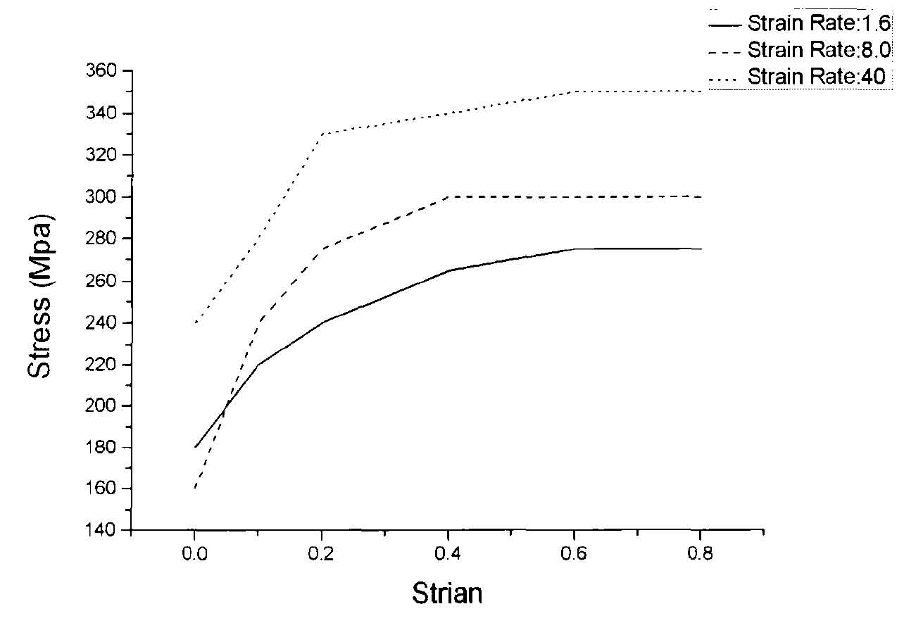
Fig. 4 shows the stress-strain curve of aisi-4120 (20CrMo steel) at 840 ℃. The figure shows the stress-strain curves under three groups of strain rates of 1.6, 8.0 and 40. It can be seen from the figure that in the range of strain value 0-0.6, the greater the strain value, the greater the required stress. Because the strain value of round bar blank is larger than that of blank with boss, the load value required for round bar blank forming is slightly larger than that of blank with boss.