
1.Obtaining Basic Gear Parameters
There are many gear parameters and there are certain connections among them. The most important one is to determine the gear center and take it as a reference. The number of teeth, indexing circle, crown circle and root circle diameter can be measured, and then other basic parameters can be obtained by formula calculation.
The accuracy of gear center positioning will directly affect the accuracy of gear measurement. Common methods of gear center positioning are: center of gravity method, least squares fitting, Hough transformation, etc.Through comparative analysis of the results of the three methods, the center of gravity method is selected.Firstly, the connected area of the gear image filled with imfill function is identified to find the center of gravity of the gear contour without center hole, that is, the center of the gear.The algorithm is fast in calculation and accurate in positioning.Then ignore the center hole to find the minimum outer rectangle of the gear profile, the average of which is the crown circle diameter of the gear.When there is no center hole, the minimum distance from gear contour to the center is the radius of the root circle. To improve the measurement accuracy, the mean of 20 minimum distances is selected as the radius of the root circle.To measure the number of teeth of a gear, draw a circle between the top circle and the root circle, design a mask template, and set the internal gray value of the circle to 0 in the binary image, while the external gray value remains unchanged. Statistics the number of connected areas z, that is, the number of teeth of the gear.
2.Measurement of pitch deviation
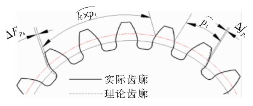
The pitch deviation is defined as the deviation between the actual pitch and the theoretical pitch on the indexing circle in the end plane.Because it is difficult to locate the datum on the indexing circle by traditional measuring method, the pitch is often measured on the circle at the middle of the tooth, which increases the error.Using machine vision to measure the pitch deviation of gears, it is possible to accurately measure the reference datum on the indexing circle [14-15].The figure shows a sketch of pitch deviation, in which three measures of pitch deviation are shown: single pitch deviation fpt, K accumulated pitch deviation FPK (k=z/8 rounded) and total accumulated pitch deviation Fpk.The algorithm is designed as follows:
(1) Draw the indexing circle with the center of gear as the circle to find the intersection point between the indexing circle and the gear tooth profile, and record it as p1, p2,…, P2z (z is the number of teeth of the gear).
(2) Obtain the angle piOpi+2 (i=1,2,…”2z-2), angle between the intersection point of the same side tooth profile and the center of the circle of the adjacent K teeth_piOpi+2k (i=1,2,…).”, 2z-2k), 1st intersection and 1st+2i intersection (i=1,2,…, z) and the angle between the center of the circle p1Op1+2i (i=1,2,…, z).
(3) Find out the corresponding pitch deviation.