1. Create gear parametric model
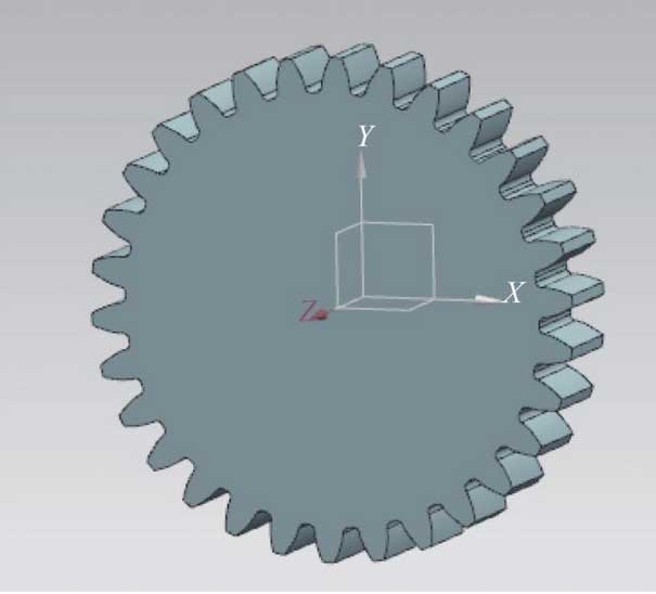
Nx software itself can generate gear model, but it can only generate the bottom features of gear structure as shown in Figure 4. Because the gear is a non parametric model, it is difficult to modify and reuse, and it cannot be designed in pairs. Therefore, according to the characteristics of gearbox gear, the development of gear virtual design system can facilitate the designers to quickly design the gearbox gear with complex structure and improve the design efficiency.

According to the design requirements of a tractor gearbox, several sets of features are extracted to create a gear parametric model, which are spur gear and helical gear, internal gear and external gear, standard gear and displacement gear, spline gear and keyway gear. The system automatically determines the gear structure according to the parameters, and the designer can also modify it according to the actual requirements.
The design parameters of the gear mainly include module, number of teeth, tooth width, pressure angle, tooth top height coefficient, top clearance coefficient and displacement coefficient. The design of the displacement gear needs to consider the matching gear parameters at the same time. The formulas of gear modeling include the diameter of the dividing circle (D1), the diameter of the root circle (DF1), the coefficient of variation of the center distance (y), the coefficient of variation of the tooth height (Δ y), the pressure angle of the end face (α T), the involute mirror angle (degree), etc. the main formulas are as follows:
d1=mz1/cosβ (1)
df1=d1-2m(ha+c-x1) (2)
y=a’0m-12m(z1+z2) (3)
Δy=x1+x2-y (4)
αt=arctan(tanαn/cosβ) (5)
degree=180(π2+2x1tanαt)/(πz1) (6)
Where: m – module, mm; Z1 – number of teeth of gear 1; Z2 – number of teeth of gear 1 pair; β – helix angle, ° ha * – coefficient of addendum; c * – coefficient of backlash; X1 – coefficient of displacement of gear 1; X2 – coefficient of displacement of gear 1 pair; A0 ‘- center distance after displacement, mm; α n – normal pressure angle, ° a.
After the gear formula is edited, the NX expression is imported and the parameters are associated in the modeling process to complete the bottom structure feature modeling of the gear, as shown in Figure 4. On the basis of the structural features of gear bottom layer, continue to create other branch features, then suppress all branch features, write suppression rules into NX expression, and then use NX software “suppressed by expression” function to control branch features. For example: establish the expression rule if (E ≥ 2 M & Da ≤ 160) (1) else (0), associate the expression with the solid gear branch feature, when Da > 160 mm, the solid gear feature branch will be in the state of suppression and non generation. For branch features, you can continue to build expressions to control the next level of branch features, such as if (30
2. Man machine system interface development
Nx 10.0 is developed by NX / open, which is the second development tool set of NX. The interface of gearbox gear man-machine system is established. The man-machine interface includes making user menu and user input dialog box. The user menu is created by menuscript, through which developers can add new menus, establish the connection between programs and NX software. The running interface of gear user menu is shown in Figure 5. The user input dialog box is created by uistyler, which is used to input the user’s design requirements, modify the relevant parameters of the gear, and establish the association between the input parameters and the gear model.
Then write a program in the environment of visual studio 2013 to associate the user input parameters with NX expression, and then control the gear parametric model. Continue to read the gear model from the model library into the NX memory, then judge and select the gear structure according to the user’s input parameters, determine the branch structure of the gear, carry out correlation control on the NX expression, finally drive NX to modify the model library gear, and get a new parametric gear after regeneration. After the input of gear parameters, click the confirm button, the system can generate gears of different structures through intelligent selection, and the user can also modify the gear structure through the dialog box.
3. Design examples and results
The interface of gearbox gear virtual design system developed on the platform of NX is shown in Figure 7. Under the guidance of gear user menu, designers can quickly complete the detailed structure design of gears.
X={X0,X1,X2,⋯,Xn} (7)
The feature parameter set of gear bottom structure is
X0=(m,z1,z2,b1,b2,α,β) (8)
The parameter set of internal spline of branch feature 1 is
X1=(m,z,α) (9)
The parameter set of external spline of branch feature 2 is
X2=(m,z,α,b) (10)
Where: xn is the nth branch characteristic parameter set; B1 is the tooth width of gear 1, mm; B2 is the tooth width of paired gear 1, mm; α is the pressure angle of spur gear or the normal surface pressure angle of helical gear, ° and B is the tooth width of external spline, mm.
The design parameters of the internal spline spur gear are assigned, and the parameter set is:
Xinner={X0,X1}={(3.5,30,42,20,20,20,0),(3,14,30)}
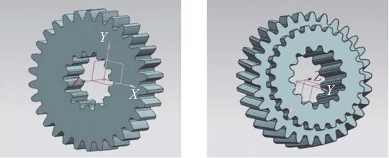
The internal spline spur gear model automatically generated by the system driven by the data set is shown in Figure 8A.
The design parameters of the internal and external spline helical gear are assigned. The parameter set is:
Xexter={X0,X1,X2}={(3,30,35,25,25,20,15),(3,14,30),(3,25,30,7)}
The model of internal and external spline helical gear automatically generated by the system driven by the data set is shown in Figure 8b.
After designing a gear, select the user input dialog box to create a pair of gears 2 button, you can continue to design the pair of gears, in order to improve the efficiency of gear design and achieve the effect of rapid design.

In the virtual design and simulation process of tractor gearbox, gear parts account for about half of the total parts of gearbox, so it is difficult to model, and there is a lot of repeated work. New designers need to spend a lot of time learning gear design knowledge, and it is difficult to ensure the accuracy and accuracy of gear model, which seriously affects the virtual simulation cycle of gearbox. The virtual design system of gearbox gear reuses the complex gear model which can be completed in a few hours by hand, and the design system can be created in a few seconds. For the complex spline gear and displacement gear which are common in tractor gearbox, it can be designed quickly and in large quantities. Designers only need to input parameters in the interface of human-machine system, and the system automatically outputs the detailed structure model of spline gear. In the virtual design of a large number of gear models of the whole machine, the complicated and repetitive modeling work of designers can be reduced, and the simulation cycle of the gearbox can be shortened.
