
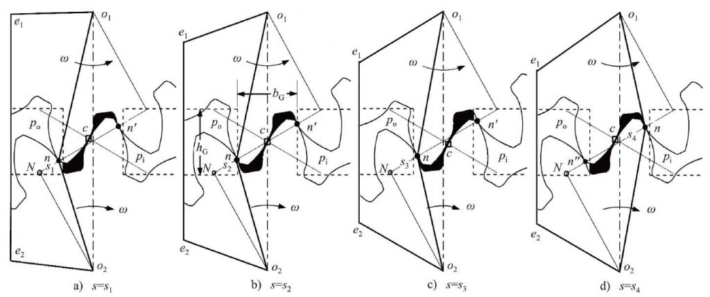
The trapping process and meshing process of the gear micropump are completely consistent with those of the commonly used gear pumps, as shown in Fig. 1, where.., □, ○ or n denote the positions of the meshing point, the backlash point and the end point of the theoretical meshing line; O1, O2 are the main and secondary gear centers; Figures 1a to 1D respectively show the transmission position when (n) is the vertex of O1 tooth, □ (c) is the node, (n ‘) is the vertex of O2 gear and. (n ″) is the vertex of O1 tooth. Figures 1a-1d and 1a-1c respectively describe the meshing process and oil trapping process. If the length of × (n). (n) is s, s corresponding to Fig. 1a-1d is S1-S4; the trapped oil volume, volume change rate and trapped oil pressure are V, DV, P, respectively

Where,
L — length of meshing line
Re, Rb — radius of top and base circle
Pb — basal node
α’ — angle of engagement
BG, Hg — the width and height of the rectangular enclosed area in the center of the double rectangular unloading groove
R ‘, RF — radius of pitch circle and root circle of gear
Velocity – ω
B — tooth width