1. Introduction
In the cement production industry, edge – driven open – gear mills play a crucial role. The Φ3.2 m×13 m edge – driven mill in a certain company is a typical example. Since its installation in October 2010, it has experienced various problems, mainly manifested in the abnormal vibration of components such as small gears, which has seriously affected the normal operation of the equipment and the production efficiency of the enterprise.
1.1 Background of the Problem
The 2# cement mill in the company started production after installation in 2010. However, the small – gear horizontal vibration was on the high side. When the ambient temperature in summer or the temperature of the cement leaving the mill increased, the maximum vibration reached 30 mm/s. This problem was not effectively resolved. In 2016, the mill – tail cylinder flange cracked. After welding repair, the vibration of the small gear, reducer, and main motor all increased. By 2019, the situation deteriorated further, with severe vibrations, frequent breakage of coupling bolts, and deformation of the coupling flange, forcing the mill to shut down for maintenance.
1.2 Significance of Solving the Problem
The normal operation of the mill is directly related to the output and quality of cement products. Unresolved problems such as cylinder flange cracks and abnormal vibrations not only lead to increased maintenance costs and downtime but also affect product quality. Therefore, finding an effective repair method for the cylinder flange is of great significance for ensuring the stable production of the enterprise.
2. Analysis of the Causes of the Problem
2.1 Installation – related Issues
When the mill was installed in 2010, the radial run – out data of the large gear ring was 1.1 mm, slightly greater than 0.25‰ of the pitch circle diameter; the face run – out data was 2.2 mm, greater than 0.35‰ of the pitch circle diameter. These values did not meet the installation technical requirements, resulting in poor meshing between the large and small gears, which laid a hidden danger for the subsequent operation of the equipment. The following table summarizes the installation data and standards:
| Installation Parameter | Measured Value | Standard Requirement | Deviation |
|---|---|---|---|
| Radial Run – out of Large Gear Ring | 1.1 mm | ≤ 0.25‰ of Pitch Circle Diameter | Exceeded |
| Face Run – out of Large Gear Ring | 2.2 mm | ≤ 0.35‰ of Pitch Circle Diameter | Exceeded |
2.2 Repair – related Issues in 2016
In June 2016, when repairing the root crack of the cylinder flange by on – line welding, the steel balls in the mill cylinder were not removed, and the influence of the equipment’s own weight was not eliminated by using a jack to lift the cylinder. When the crack was gouged with a carbon rod, the flange at the groove deformed and became out – of – round under the weight of the mill cylinder. As a result, the face run – out of the large gear ring increased to 3.4 mm, further deteriorating the meshing of the large and small gears, and causing large axial vibrations of the reducer and small – gear bearing seat, and frequent breakage of connecting bolts.
3. On – line Repair Process
3.1 Measurement of Large Gear Ring Flange Run – out
The first step of the repair process is to measure the face and radial run – out data of the large gear ring flange. The large gear cover is disassembled, and the large gear is removed. The flange surface is cleaned and evenly divided into 16 equal parts around the circumference. A dial indicator is used to measure the face and radial run – out. The measured data is shown in Table 2:
| Serial Number | Face Data (μm) | Radial Data (μm) |
|---|---|---|
| 1 | 1970 | 4440 |
| 2 | 3020 | 4820 |
| 3 | 3620 | 4670 |
| 4 | 3850 | 4300 |
| 5 | 3620 | 4500 |
| 6 | 3400 | 3800 |
| 7 | 2500 | 3800 |
| 8 | 1750 | 3600 |
| 9 | 1700 | 3250 |
| 10 | 1950 | 3350 |
| 11 | 2540 | 4030 |
| 12 | 3180 | 3540 |
| 13 | 3320 | 3600 |
| 14 | 3360 | 3150 |
| 15 | 3120 | 3600 |
| 16 | 2480 | 3500 |
| 17 | 900 | 3000 |
| 18 | 460 | 3370 |
| 19 | 460 | 4050 |
| 20 | 810 | 4030 |
The radial data is basically within the standard range, but the face measurement shows large fluctuations, with the maximum value at the 9# point being 3.85 mm and the minimum value at the 18# point being 0.46 mm. The data of the remaining 14 points are between 0.81 – 3.62 mm, indicating a large run – out.
3.2 Surfacing of the Cylinder Flange
The cylinder flange is surfaced with the highest point of the flange face as the reference point. Based on the highest point and combined with the measured data, the other low – point positions are welded with wires. CE71T – 1 welding wire is selected because it has a stable arc, less spatter, easy slag removal, and beautiful weld formation, ensuring good material matching and fusion performance with the cylinder flange. Carbon dioxide gas – shielded welding is used to ensure the crack – surfacing process, reduce the amount of deformation, and increase the strength.
The surfacing process has strict control requirements. It is not allowed to surface to the required thickness at one time. The surfacing speed is controlled at about 28 mm/s, and the single – layer surfacing thickness is controlled within 1.5 mm. After multiple – layer surfacing, the required thickness of 4.5 mm is reached. After surfacing, a thickness gauge is used for preliminary measurement to ensure that the 16 points basically reach the measured value of the highest point. Then, the flange edge is initially turned about 30 mm inward with a lathe to make the flange face smooth enough for the dial – indicator measurement of the face run – out. When the face run – out data is within 3 mm, it is ready for on – line turning.
3.3 Installation and Adjustment of the Turning Device
The traditional lathe is simply modified, and the turning device is installed above the small gear. The turning position and tools are adjusted properly. The grinding head and grinding – tail sealing covers are removed and separated from the hollow shaft of the cylinder to ensure no contact and friction during rotation. A working platform is made at the grinding – tail hollow shaft, and the auxiliary transmission reducer and motor of the mill are installed on this platform. A 19 – tooth transmission gear is installed on the output shaft of the auxiliary – transmission reducer to provide kinetic energy for the rotation of the cylinder.
An 89 – tooth gear is fixed on a 30 – mm – thick steel plate, and the steel plate is fixed on the flange bolts of the outlet – grinding hollow shaft. Then, the meshing degree between the 19 – tooth gear at the output end of the auxiliary – transmission reducer and the 89 – tooth gear on the outlet – grinding hollow shaft is adjusted to ensure good cooperation. The speed of the auxiliary – transmission motor of the mill is controlled by a frequency – converter to ensure that the rotation speed is adjustable. A simple limit device to prevent the cylinder of the mill from moving axially is made at the grinding head to ensure that the cylinder does not shift during the rotation process. A limit support frame is made at the grinding – head base, and the feed port of the hollow shaft is closed with a 20 – mm – thick steel plate. M58 bolts and nuts are welded and fixed on the support frame, and the bolt screws are used as jacking – adjustment screws to control the movement of the cylinder from the grinding – tail to the grinding – head. These measures can prevent the horizontal shift of the mill cylinder and ensure its rotation.
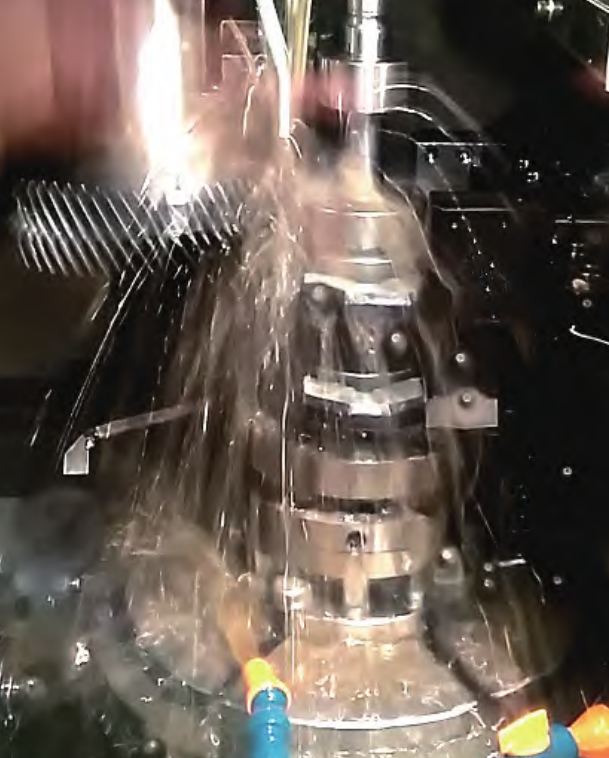
3.4 Turning and Measurement of the Cylinder Flange
After the preparation work is completed, the turning process begins. Since the surface of the flange after surfacing is rough, the turning speed should not be too fast at the beginning. The frequency of the drive motor (auxiliary – transmission motor) is controlled at about 25 Hz, approximately 0.5 r/min, and turning is carried out at this speed for about 16 hours. When the high points on the flange surface are turned off and the end face is basically flat, the rotation speed of the cylinder is increased. The frequency of the drive motor (auxiliary – transmission motor) is controlled at about 45 Hz, approximately 1 r/min, and turning is carried out at this speed for about 48 hours.
After the high and low points on the flange face are turned off, the end face is smooth and regular. The end face is evenly divided into 16 equal parts, and a dial indicator is used to measure the data of the 16 points. The maximum difference is controlled within 100 μm. After the end – face turning is completed, the radial turning begins. Referring to the end – face turning steps, the turning is carried out first slowly and then quickly. After about 24 hours, the turning is completed, and the radial run – out data is measured. The maximum difference is controlled within 200 μm.
3.5 Installation of Gear Rings and Adjustment of Meshing
After the turning process is completed, the large and small gear rings are installed. The tooth – tip clearance and side clearance are measured, and the meshing degree is adjusted. The concentricity of the small gear and the reducer, as well as the concentricity of the reducer and the motor, are verified in sequence. The maximum difference is controlled within 20 μm. After the verification is completed, the turning platform and turning equipment are removed, and the site is cleaned. After starting the machine, the vibration values of the small – gear bearing seat, the output shaft of the reducer, the input shaft of the reducer, and the motor are all within 10 mm/s, and the motor current fluctuation value is within 20 A, ensuring stable overall operation.
4. Key Points and Precautions in the Repair Process
4.1 Prevention of Deformation during Welding
For heavy – duty equipment such as mills, before grooving and welding at the flange crack, measures must be taken to prevent deformation of the repair position caused by the weight of the equipment itself. This can be achieved by removing the steel balls in the cylinder, using a jack to lift the cylinder to eliminate the influence of gravity, or other appropriate methods.
4.2 Control of Welding Process
During the repair process, the groove should not be gouged too long at one time, and the welding speed should not be too fast. Timely stress – relief measures should be taken during welding to reduce the internal stress of the welded part and prevent cracks and deformation.
4.3 Precision Control in Turning and Assembly
In the turning process of the cylinder flange, strict control of parameters such as turning speed and measurement accuracy is required to ensure that the end – face and radial run – out meet the requirements. During the installation of gear rings and the adjustment of meshing, the concentricity and meshing clearance should be accurately measured and adjusted to ensure the normal operation of the equipment.
5. Effect and Significance of On – line Repair
5.1 Long – term Stable Operation
After on – line repair, the cylinder flange of the cement mill has been in use for 4 years without any abnormalities. This shows that the on – line repair method is effective and can ensure the long – term stable operation of the equipment, reducing the frequency of maintenance and improving production efficiency.
5.2 Cost – saving and Time – saving
With the development of science and technology, on – line surfacing and turning technologies have become more and more mature. On – line repair of production equipment eliminates the need to remove the equipment and return it to the factory for repair, saving a lot of transportation costs, repair time, and production – stoppage losses. It provides a more convenient and cost – effective solution for enterprise equipment maintenance.
6. Conclusion
The on – line repair of the cylinder flange of the edge – driven open – gear mill is a complex but effective process. Through in – depth analysis of the causes of problems, strict implementation of the repair process, and attention to key points and precautions, the stable operation of the equipment can be restored. The successful application of this on – line repair technology not only solves the actual problems of enterprises but also provides valuable experience for the repair of similar equipment in the industry. As technology continues to advance, on – line repair methods are expected to play an even greater role in ensuring the normal operation of industrial production equipment.
In future research and practice, more attention can be paid to the improvement of repair materials and techniques, as well as the development of more intelligent measurement and control systems to further improve the efficiency and quality of on – line repair.