
The final drive, or main reducer, is a critical component within a vehicle’s rear axle assembly, tasked with the fundamental role of torque multiplication and speed reduction. Its performance, particularly in terms of the vibration and noise it generates, is a paramount indicator of the overall Noise, Vibration, and Harshness (NVH) characteristics of a vehicle. In the development of modern passenger and crossover vehicles, achieving superior NVH performance is essential for ride comfort and perceived quality. One primary source of vibration within the final drive assembly originates from the meshing action between the hypoid driving pinion and the driven ring gear. This meshing induces dynamic forces that are transmitted through the supporting structures, predominantly the bearing systems.
The rigidity and configuration of the bearing support system for the gear shafts, especially the driving pinion shaft, are therefore of utmost importance. The span distance between the two supporting bearings on the pinion shaft directly influences the system’s deflection under load, thereby affecting the alignment and contact pattern of the gear mesh. An inappropriate bearing span can lead to excessive deflection of the gear shafts, resulting in edge loading, increased transmission error, and consequently, elevated vibration and gear whine. This study focuses on the theoretical calculation and multi-body dynamics simulation to determine the optimal bearing span for the driving pinion in a final drive system. The objective is to enhance the overall system stiffness of the pinion-bearing assembly, improve meshing conditions, and ultimately reduce operational vibration and noise.
Fundamentals of Gear-Bearing System Dynamics
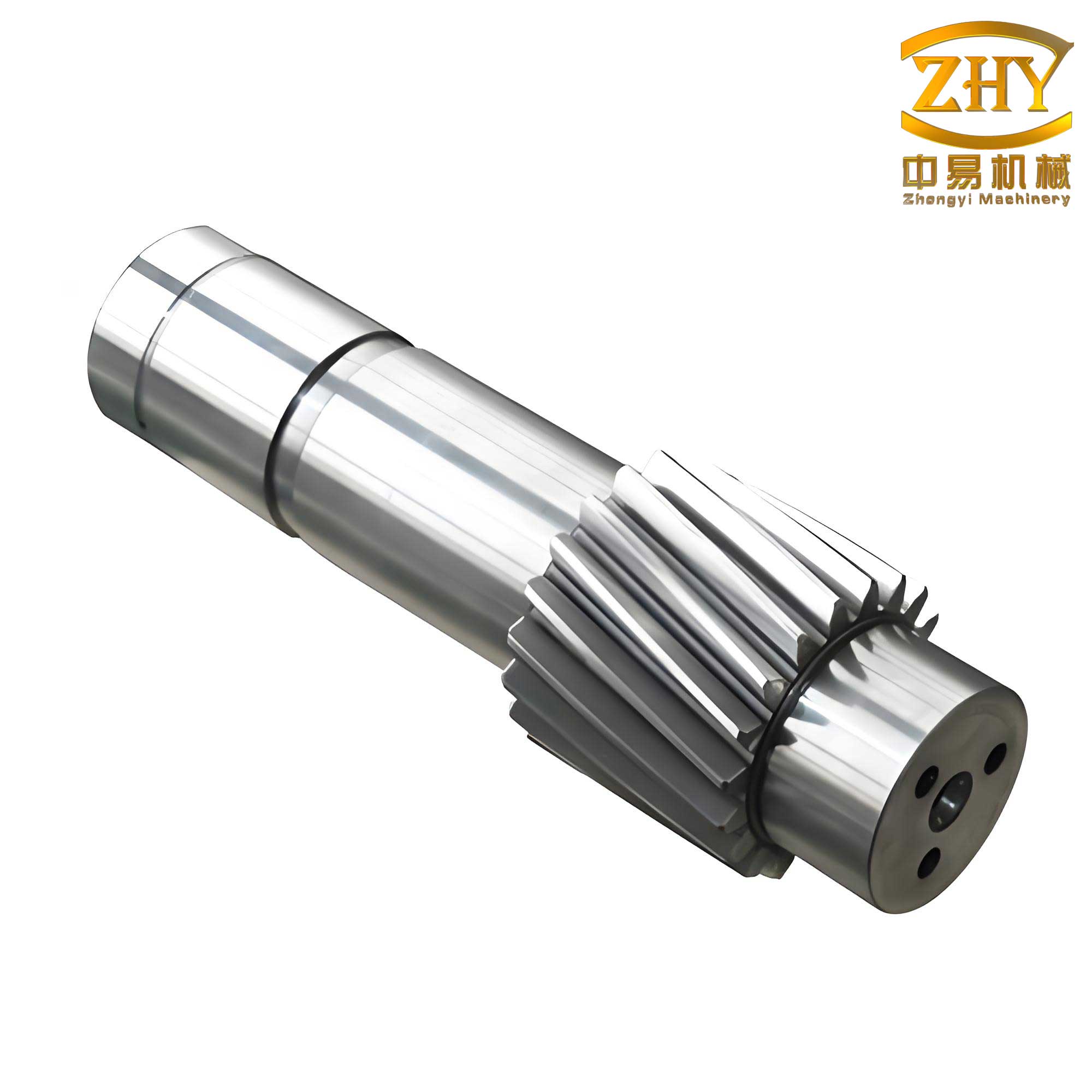
The driving pinion, supported by two tapered roller bearings, can be modeled as a statically indeterminate beam. The deflection at the pinion head, where the meshing force is applied, is a composite of two primary components: the bending of the pinion shaft itself (elastic shaft) and the elastic deformation of the supporting bearings. Minimizing this total deflection is synonymous with maximizing the system’s static stiffness, which is a key factor in controlling gear mesh excitations.
Consider the pinion shaft as a cantilevered beam supported by two bearings. The distance from the pinion head (point of force application) to the nearer bearing is defined as the overhang, denoted by $$a$$. The distance between the centers of the two supporting bearings is defined as the bearing span, denoted by $$L$$. The total deflection $$\delta$$ at the pinion head under a meshing force $$F$$ is the sum of the shaft deflection $$\delta_1$$ and the bearing deflection $$\delta_2$$.
Theoretical Framework for Optimal Span Calculation
1. Deflection of the Pinion Shaft (Assumed Rigid Bearings)
Assuming the bearings are perfectly rigid, the pinion shaft deflects as a combination of a simply supported beam (between the bearings) and a cantilever beam (the overhang section). The force $$F$$ at the pinion head can be translated to the bearing plane, resulting in a force and a moment. The deflection at the pinion head due to shaft bending alone is given by:
$$\delta_1 = \frac{F a^2}{3EI}(L + a)$$
where:
$$E$$ is the modulus of elasticity of the shaft material,
$$I$$ is the area moment of inertia of the pinion shaft cross-section.
2. Deflection due to Bearing Compliance (Assumed Rigid Shaft)
Conversely, assuming the pinion shaft is perfectly rigid, the displacement at the pinion head arises solely from the elastic deformation of the bearings. The reactions at the front (nearer) and rear bearings, $$R_1$$ and $$R_2$$ respectively, are:
$$R_1 = F(1 + \frac{a}{L}), \quad R_2 = F(\frac{a}{L})$$
If $$K_1$$ and $$K_2$$ are the radial stiffness values of the front and rear bearings, their respective deflections are $$y_1 = R_1 / K_1$$ and $$y_2 = R_2 / K_2$$. Using geometric relations, the pinion head deflection is:
$$\delta_2 = y_1(1 + \frac{a}{L}) + y_2(\frac{a}{L}) = \frac{F}{K_1} \left[ 1 + \frac{K_1}{K_2} \frac{a^2}{L^2} + \frac{2a}{L} \right]$$
3. Total Deflection and Optimal Span Condition
The total deflection of the system, considering both elastic gear shafts and elastic bearings, is the superposition:
$$\delta = \delta_1 + \delta_2 = \frac{F a^3}{3EI}(\frac{L}{a} + 1) + \frac{F}{K_1} \left[ 1 + \frac{K_1}{K_2} \frac{a^2}{L^2} + \frac{2a}{L} \right]$$
The optimal bearing span $$L_0$$ is the value that minimizes this total deflection, found by setting the derivative with respect to $$L$$ to zero: $$d\delta / dL = 0$$. Solving this condition yields the following cubic equation:
$$L_0^3 – mL_0 – n = 0$$
where the coefficients $$m$$ and $$n$$ are defined as:
$$m = \frac{6EI}{a K_1}, \quad n = \frac{6EI}{K_1}(1 + \frac{K_1}{K_2})$$
This cubic equation has a unique positive real root. A square root iteration method provides an efficient and accurate numerical solution. Defining $$Y = m n^{-2/3}$$ and $$L_0 = X \sqrt[3]{n}$$, the equation transforms to:
$$X^3 – YX – 1 = 0$$
The convergent iterative formula is:
$$X_{i+1} = \sqrt{Y + \frac{1}{X_i}}$$
After convergence to a stable value of $$X$$, the optimal span is calculated as $$L_0 = X \sqrt[3]{n}$$.
Calculation of Bearing Radial Stiffness
A critical input for the optimal span calculation is the radial stiffness of the tapered roller bearings. The stiffness is non-linear and depends on preload and geometry. For a tapered roller bearing under axial preload $$F_a$$, the relationship between the normal load $$Q$$ on a roller and the total elastic approach $$\delta$$ between the inner and outer races at the contact is empirically given by:
$$\delta = 0.0766 \frac{Q^{0.9}}{l_a^{0.8}}$$
where $$l_a$$ is the effective length of the roller. The axial load per roller is $$F_a / (Z \sin \alpha)$$, where $$Z$$ is the number of rollers and $$\alpha$$ is the contact angle. The axial deflection $$\delta_a$$ can be derived as:
$$\delta_a = \frac{\delta}{\sin \alpha} = \frac{0.0766 F_a^{0.9}}{Z^{0.9} \sin^{1.9}\alpha \cdot l_a^{0.8}}$$
When a radial load $$F_r$$ is applied, causing a radial displacement $$\delta_r$$, the load distribution around the bearing changes. The radial stiffness $$K_r$$ is defined as $$dF_r/d\delta_r$$. A simplified yet accurate approximation for the radial stiffness under a dominating axial preload can be derived, yielding:
$$K_r = \frac{dF_r}{d\delta_r} \approx 7.253 \frac{F_a^{0.1} l_a^{0.8} Z^{0.9} \cos^2 \alpha}{\sin^{0.1} \alpha}$$
For the specific bearings in this study (305 and 306 series), with an axial preload $$F_a$$ = 70,000 N, the radial stiffness values are calculated as follows:
| Bearing Designation | Effective Roller Length, $$l_a$$ (mm) | Number of Rollers, $$Z$$ | Contact Angle, $$\alpha$$ (°) | Calculated Radial Stiffness, $$K$$ (N/µm) |
|---|---|---|---|---|
| 305 Bearing (Front) | 11.0 | 16 | 20 | $$K_1$$ = 2,379.5 |
| 306 Bearing (Rear) | 14.6 | 17 | 20 | $$K_2$$ = 1,796.5 |
Numerical Solution for Optimal Span
With the bearing stiffness values known, and given the pinion shaft diameter of 30 mm (yielding $$I = \pi d^4 / 64 = 7.952 \times 10^4 \text{ mm}^4$$), and material modulus $$E = 2.08 \times 10^5 \text{ N/mm}^2$$, the parameters for the optimal span equation are computed. The overhang $$a$$ is a fixed design parameter obtained from the gear geometry.
$$m = \frac{6EI}{a K_1} = 1263.9, \quad n = \frac{6EI}{K_1}(1 + \frac{K_1}{K_2}) = 96952$$
$$Y = m n^{-2/3} = 0.5989$$
Using the iterative method with an initial guess $$X_0 = 1.17$$:
$$X_1 = \sqrt{Y + \frac{1}{X_0}} = 1.1953$$
$$X_2 = \sqrt{Y + \frac{1}{X_1}} = 1.1975$$
$$X_3 = \sqrt{Y + \frac{1}{X_2}} = 1.1975$$
The value converges to $$X = 1.1975$$. Therefore, the optimal bearing span is:
$$L_0 = X \sqrt[3]{n} = 1.1975 \times \sqrt[3]{96952} \approx 55.01 \text{ mm}$$
The theoretical calculation thus predicts that a bearing span of approximately 55 mm will minimize the deflection of the gear shafts assembly under load, thereby maximizing system stiffness.
Multi-Body Dynamics Simulation for Validation
To validate the theoretical finding, a multi-body dynamics (MBD) model of the complete final drive assembly was developed. The model includes the driving pinion, driven ring gear, differential case, and the supporting housing structures simplified as bearing seats. The primary components, especially the gear shafts and gear bodies, were modeled according to precise dimensional specifications.
1. Model Setup and Contact Parameters
All parts were assigned appropriate material properties (elastic modulus, density, Poisson’s ratio). Critical interaction pairs were defined with non-linear contact force models based on the Hertzian contact theory. The contact stiffness coefficient $$K$$ is given by:
$$K = \frac{4}{3} R^{1/2} E^*$$
where $$\frac{1}{R} = \frac{1}{R_1} + \frac{1}{R_2}$$ ($$R_1, R_2$$ are contact body radii) and $$\frac{1}{E^*} = \frac{1-\mu_1^2}{E_1} + \frac{1-\mu_2^2}{E_2}$$.
This formulation was used to calculate the stiffness for the gear mesh and for all roller-to-raceway contacts in the bearings. The relevant parameters for the hypoid gear pair and the bearings are summarized below.
| Contact Pair | Equivalent Radius, $$R$$ (mm) | Equivalent Modulus, $$E^*$$ (N/mm²) | Contact Stiffness Coeff., $$K$$ |
|---|---|---|---|
| Pinion-Ring Gear Mesh | 14.88 | 1.104 × 10⁵ | 5.68 × 10⁵ |
| 305 Bearing (Inner Race-Roller) | Derived from CAD | 2.31 × 10⁵ | 6.47 × 10⁵ |
| 305 Bearing (Outer Race-Roller) | Derived from CAD | 2.31 × 10⁵ | 7.84 × 10⁵ |
| 306 Bearing (Inner Race-Roller) | Derived from CAD | 2.31 × 10⁵ | 7.20 × 10⁵ |
2. Simulation Protocol
The housing was fixed to ground. Revolute joints were applied to the gear shafts. A constant load torque of 500 Nm was applied to the differential case (resisting ring gear rotation). The driving pinion was subjected to a range of constant rotational speeds from 800 rpm to 5000 rpm, simulating various vehicle operating conditions. The bearing span $$L$$ was treated as a variable. Six different configurations were simulated: $$L$$ = 54, 55, 56, 57, 58, and 59 mm. For each configuration and each speed, the dynamic response was analyzed.
3. Metrics for Vibration Assessment
Key dynamic response metrics were extracted from the simulation results for the driven ring gear, as its motion reflects the quality of the gear mesh:
- Vertical (Y-direction) Acceleration: Directly related to structure-borne vibration and noise radiation. Root Mean Square (RMS) and Peak-to-Peak values were analyzed.
- Angular Acceleration: Indicates torsional vibration and fluctuations in the rotational motion, contributing to gear rattle and whine.
- Angular Velocity Fluctuation: Measures the deviation from ideal constant rotational speed, directly linked to transmission error.
- Gear Mesh Force (Y-component): The dynamic force normal to the gear mesh plane is a primary excitation source for the system.
Simulation Results and Comparative Analysis
The simulation data was processed to compare the vibration performance across the six different bearing span configurations. The results consistently indicated that a span of 55 mm provided the most favorable dynamic behavior.
1. Vertical Acceleration of the Ring Gear
The RMS of the vertical acceleration for the ring gear was lowest for the 55 mm span across most speed points, indicating lower overall vibration energy. The peak-to-peak acceleration, representing the severity of transient shocks, was also minimized at this span for mid-range speeds.
| Pinion Speed (rpm) | Bearing Span = 54 mm RMS (m/s²) | Bearing Span = 55 mm RMS (m/s²) | Bearing Span = 56 mm RMS (m/s²) | Bearing Span = 57 mm RMS (m/s²) | Bearing Span = 58 mm RMS (m/s²) | Bearing Span = 59 mm RMS (m/s²) |
|---|---|---|---|---|---|---|
| 1500 | 42.1 | 38.5 | 40.2 | 43.8 | 45.7 | 47.9 |
| 3000 | 118.7 | 105.3 | 112.4 | 121.6 | 128.9 | 135.2 |
| 5000 | 256.4 | 248.1 | 251.7 | 259.8 | 267.5 | 274.8 |
2. Ring Gear Angular Velocity and Acceleration
The stability of the ring gear’s rotation was best at the 55 mm span. The mean angular velocity was closest to the ideal kinematic value, and the fluctuation (difference between max and min) was the smallest. Similarly, the mean and peak-to-peak values of angular acceleration were minimized, suggesting smoother torque transmission and lower torsional vibration levels. This optimal behavior stems from the reduced deflection of the gear shafts, which maintains better gear alignment.
| Performance Metric @ 3000 rpm | Span = 54 mm | Span = 55 mm | Span = 56 mm | Span = 57 mm | Span = 58 mm | Span = 59 mm |
|---|---|---|---|---|---|---|
| Mean Ang. Velocity (rad/s) | 31.38 | 31.41 | 31.40 | 31.37 | 31.35 | 31.33 |
| Ang. Velocity Fluctuation (rad/s) | 0.85 | 0.72 | 0.78 | 0.88 | 0.94 | 1.01 |
| RMS Ang. Acceleration (rad/s²) | 452 | 398 | 425 | 468 | 502 | 531 |
3. Dynamic Gear Mesh Force
The Y-component of the dynamic mesh force, a direct excitation source, was analyzed. The RMS value of this force was consistently lower for the 55 mm span configuration across all simulated speeds. A lower dynamic mesh force implies reduced dynamic loading on the gear teeth and the supporting gear shafts and bearings, leading to lower vibration generation and potentially longer component life.
| Pinion Speed (rpm) | RMS Mesh Force (Y), L=54mm (kN) | RMS Mesh Force (Y), L=55mm (kN) | RMS Mesh Force (Y), L=56mm (kN) |
|---|---|---|---|
| 2000 | 4.12 | 3.89 | 4.05 |
| 4000 | 8.95 | 8.31 | 8.70 |
Discussion
The remarkable correlation between the theoretical optimal span of 55.01 mm and the simulation results confirming the 55 mm span as the best performer validates the underlying mechanical principle. The optimization theory targets the minimization of static deflection at the pinion head, which is a proxy for maximizing the system’s static stiffness. A stiffer support system for the gear shafts directly translates into improved dynamic performance because it:
- Reduces Transmission Error: Less deflection under fluctuating mesh forces means the actual position of the gear teeth deviates less from their ideal theoretical path. This minimizes one of the fundamental excitations in geared systems.
- Improves Contact Pattern Stability: A rigidly supported pinion maintains a consistent and optimal contact pattern on the gear teeth under varying loads, preventing edge loading and the associated stress concentrations and noise.
- Attenuates Dynamic Amplification: A stiffer system generally has higher natural frequencies. By moving these frequencies away from the dominant excitation frequencies (gear mesh frequency and its harmonics), the risk of resonance and the associated amplification of vibration is reduced.
The simulation metrics collectively paint a clear picture: the 55 mm span configuration results in the lowest vibration acceleration levels, the smoothest rotational motion (minimal angular velocity and acceleration fluctuations), and the lowest dynamic mesh forces. This comprehensive improvement across multiple dynamic indices underscores that optimizing the bearing span is not merely a theoretical exercise but has tangible, significant benefits for the NVH performance of the final drive assembly. The design of the gear shafts and their support system is therefore a critical aspect of final drive development.
Conclusion
This study successfully demonstrated a combined analytical and simulation approach to optimize the bearing support span for the driving pinion in an automotive final drive. A theoretical model was developed to calculate the optimal span by minimizing the total deflection of the pinion-bearing system, accounting for the elasticity of both the gear shafts and the bearings. The critical input of bearing radial stiffness was derived from first principles. The theoretically optimal span was calculated to be approximately 55 mm.
This result was rigorously validated through detailed multi-body dynamics simulations of the complete final drive assembly under operational speeds and loads. Six different bearing spans were evaluated based on key vibration performance metrics, including gear acceleration, rotational stability, and dynamic mesh forces. The simulation results conclusively showed that the 55 mm span configuration yielded the best overall dynamic performance, confirming the theoretical prediction.
Therefore, optimizing the bearing span is a highly effective design strategy to enhance the system stiffness of the pinion-gear shafts-bearing assembly. This leads to improved gear meshing conditions, reduced dynamic excitation, and ultimately, lower vibration and noise radiation from the final drive. Implementing this finding in the design phase can significantly contribute to achieving superior vehicle NVH characteristics and enhanced passenger comfort, which are essential competitive factors in the modern automotive industry, especially for crossover and utility vehicles.