As one of the most widely used transmission forms in mechanical equipment, helical gear transmission has a significant impact on the normal operation of the entire equipment due to its transmission performance. In order to improve the transmission performance of helical gear pairs, researchers have conducted in-depth research on the adhesion state of the tooth surface under dry friction, tooth root cracks, and vibration characteristics of mining reducers. However, most of the current research has not considered the influence of shaft deformation factors on the meshing contact of helical gears. Based on this, analyze and optimize the influence of the distribution of the helical gear shaft on the meshing contact.
1. Basic parameters and load capacity calculation of helical gears
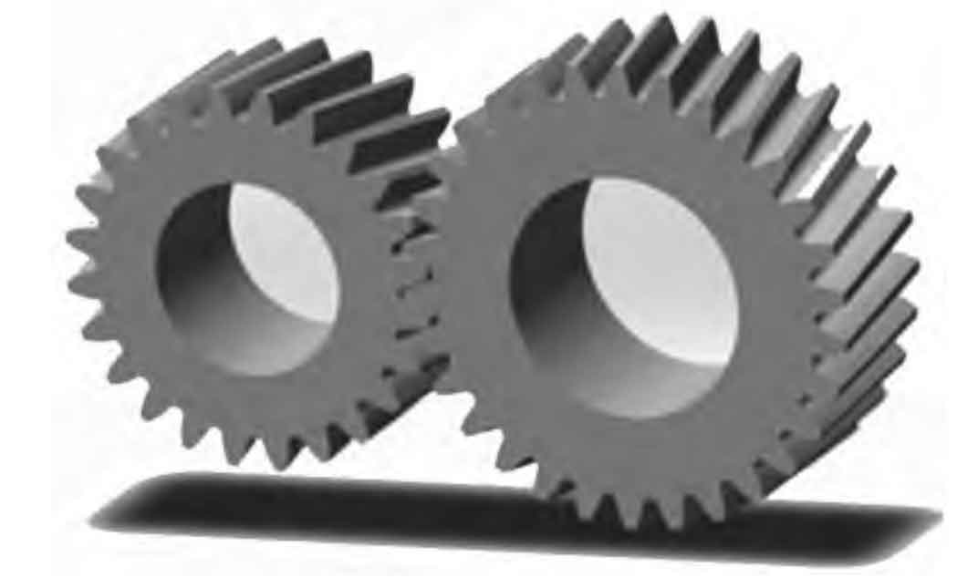
Taking a certain cutting reducer helical gear pair and its transmission bearing as the research object, the number of active gear teeth z1=20, the number of passive gear teeth z2=32, the modulus is 6 mm, the helix angle is 10 °, the pressure angle is 20 °, the tooth width is 75 mm, the modification coefficients are 0.559 3 and 0.583 4 respectively, and the quality level is 6 (ISO 1328); Establish the corresponding helical gear pair model as shown in Figure 1.
Contact stress of helical gear meshing:

Nominal tooth contact stress:

Helical gear tooth ratio:

In the formula:
KA – utilization coefficient, taking KA=1.25;
KV – dynamic load coefficient, taken as KV=1.075;
KH β——— The tooth load distribution coefficient for mild contact calculation, taken as KH β= 1.0;
KH α——— The load distribution coefficient between teeth for contact strength calculation, taken as KH α= 1.037 5;
ZB, ZD – single pair tooth meshing coefficient, taken as ZB=1.03, ZD=1.00;
Ft – nominal tangential force on the end face indexing circle, Ft=47 528.1 N;
B — Working tooth width (relatively small value), b=75 mm;
D1- diameter of the small gear indexing circle, d1=quasi 160 mm;
ZH – Node area coefficient, taken as ZH=2.173;
ZE – Elastic coefficient, ZE=189.812;
Z ε——— Coincidence coefficient, Z ε= 0.916;
Z β——— Spiral angle coefficient, Z β= 1.008.
Calculated, σ H1=1 175.01 MPa, σ H2=1 140.79 MPa. The allowable tooth contact stress of the known material is 1455 MPa and 1476 MPa, respectively; The safety factors for tooth contact stress are 1.25 and 1.30, respectively.
2. Simulation analysis of helical gear meshing contact
(1) Simulation analysis of meshing of helical gear pairs without considering the shaft system
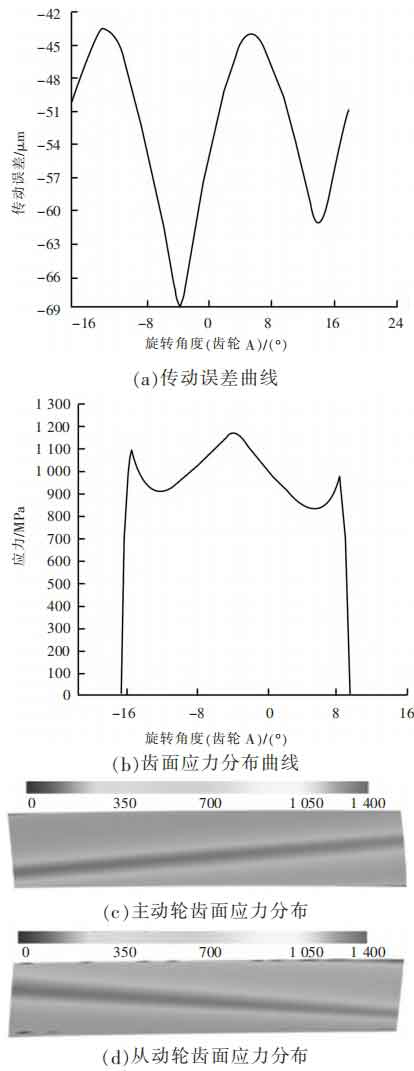
Firstly, a separate simulation analysis was conducted on the meshing contact of the helical gear pair. The transmission error curve and the stress distribution on the tooth surfaces of the driving and driven gears are shown in Figure 2. As shown in Figure 2, the transmission error interval is [-69, -43] μ m. The maximum contact stress is 1173 MPa, and the stress distribution on the tooth surface is uniformly inclined across the tooth surface.
(2) Simulation analysis of helical gear pair meshing considering shaft system
The model of the helical gear shaft system is shown in Figure 3.

The transmission error curve of the helical gear pair considering the shaft system and the stress distribution on the tooth surfaces of the driving and driven gears are shown in Figure 4. As shown in Figure 4, the transmission error interval is [-74, -49] μ m. The maximum contact stress is 1158 MPa, and the stress distribution on the tooth surface is skewed across the tooth surface, resulting in severe stress distribution deviation.
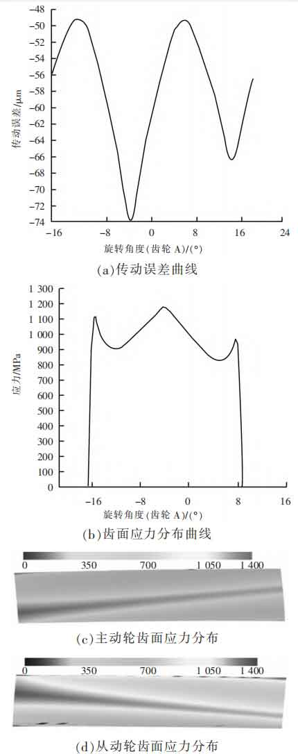
Comparing Figures 2 and 4, it can be seen that the influence of the shaft system on the meshing contact of the helical gear pair is mainly manifested as: ① the transmission error range continues to expand; ② The stress distribution on the tooth surface is severely unbalanced.
3. Optimization design of tooth contact
(1) Tooth profile modification
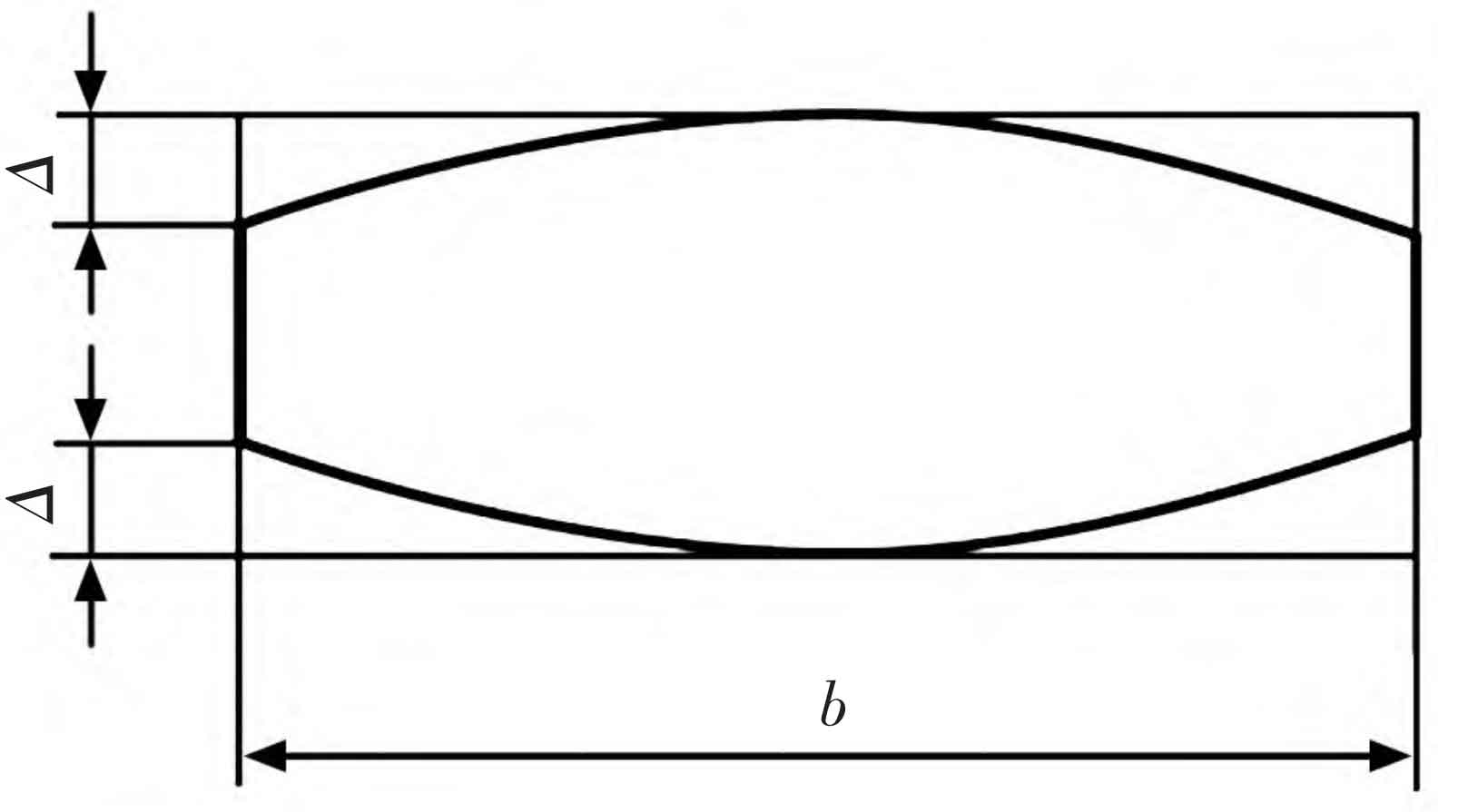
In order to reduce the elastic deformation caused by tooth loading and meshing interference and impact caused by manufacturing errors, improve the lubrication state of the tooth surface, and improve the partial stress concentration at the tooth top and root, helical gears are subjected to tooth profile modification (tooth profile elastic modification and tooth profile drum modification) as shown in Figure 5.
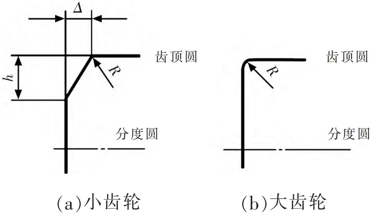
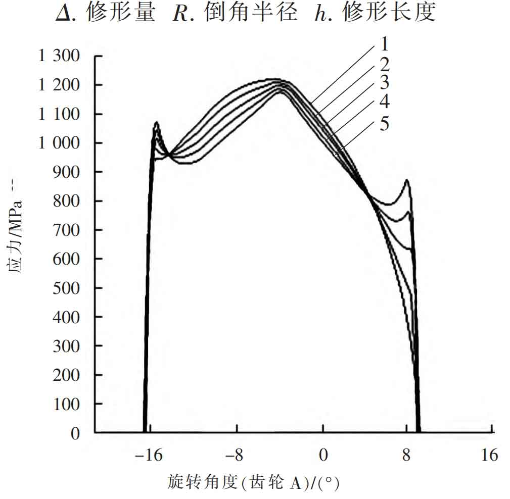
Firstly, according to the Mechanical Design Manual, the method for determining the amount of tooth profile elastic deformation modification is selected as Method 1: Δ= 0.025~0.040 mm, R=0.75 mm, h=2.1~2.7 mm; Next, choose the drum shaped tooth profile for modification, with a modification amount of 10 for each μ m. 20 μ m. 30 μ m. 40 μ m. 50 μ Analyze the meshing contact situation of the tooth surface under different modification amounts, as shown in Figure 6; It can be clearly seen from Figure 6 that as the amount of tooth profile modification gradually increases, the stress concentration at both ends of the tooth surface suddenly decreases, and the maximum contact stress on the tooth surface slowly increases. Therefore, 30 can be selected μ M is used as the amount of tooth profile modification, as shown in Figure 7.
(2) Tooth alignment correction
In order to obtain a more uniform distribution of tooth load and improve contact spots, it is necessary to perform tooth profile modification on high-speed and heavy-duty wide helical (spur) gears. The linear velocity of the helical gear pair in the model is 9.3 m/s, which is much less than 100 m/s, so the thermal deformation modification of the helical gear teeth is not considered; The modification amount is only calculated based on elastic deformation, and the recommended value is Δ= 0.013~0.035 mm.
To determine a more accurate amount of tooth alignment drum shape modification, within the recommended modification range [13, 35] μ Select 13 for each m μ m. 18 μ m. 23 μ m. 28 μ m. 33 μ m. 35 μ Preliminary simulation analysis of helical gear meshing was conducted, and the distribution of contact stress on the tooth surface under different modification amounts was obtained as shown in Figure 8.
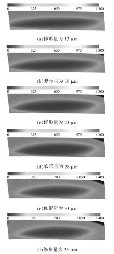
From Figure 8, it can be clearly seen that as the amount of drum shaped tooth modification increases, the stress contact spot on the tooth surface gradually approaches the center of the tooth surface, and the contact stress on the tooth surface slowly increases, resulting in a significant improvement in the stress distribution on the tooth surface.
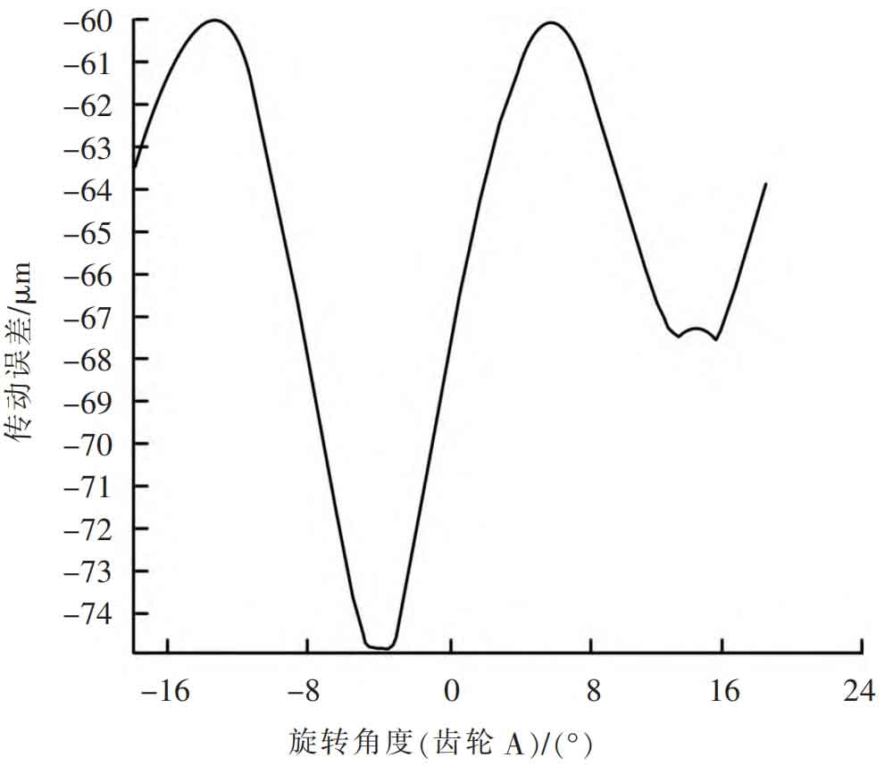
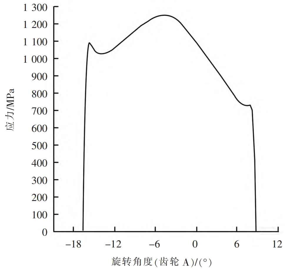
Select a shaping amount of 28 μ The modification plan of m yields the transmission error curve as shown in Figure 9, and the tooth surface stress distribution curve is shown in Figure 10. At this time, the transmission error interval is [-75, -61] μ m. Smooth transmission; The maximum contact stress on the tooth surface is 1243 MPa, and the contact spot situation on the tooth surface has been greatly improved. At the same time, considering the manufacturing situation and cost, this plan was ultimately chosen for profile modification design to improve the meshing contact performance of helical gears.
4. Conclusion
A detailed analysis is conducted on the meshing performance of the helical gear pair before and after considering the influence of the shaft system. The method of helical gear modification is adopted to optimize the design of the helical gear pair. By selecting a reasonable modification method and amount, the distribution of contact spots on the tooth surface and the transmission error are improved. The transmission error is reduced by 24% μ M becomes 15 μ m. A decrease of 37.5%; The uneven distribution of meshing contact spots on the tooth surface caused by deformation of the shaft system has been improved through modification, comprehensively enhancing the transmission performance of the helical gear pair.
