
In the field of high-performance power transmission systems, herringbone gears are widely recognized for their superior load-carrying capacity, smooth operation, and self-balancing axial forces. As a researcher deeply involved in gear dynamics and optimization, I have extensively studied the challenges associated with herringbone gears, particularly the uneven load distribution between left and right tooth flanks caused by manufacturing inaccuracies, assembly errors, and system deformations. This asymmetry often leads to localized high stresses, increased vibration, and potential failure modes such as scuffing, which compromise the reliability and lifespan of critical applications like helicopter drivetrains. Therefore, in this work, I propose a comprehensive compound modification design methodology aimed at optimizing the load distribution and enhancing the meshing performance of herringbone gears through a combination of axial floating strategies and tailored tooth surface modifications.
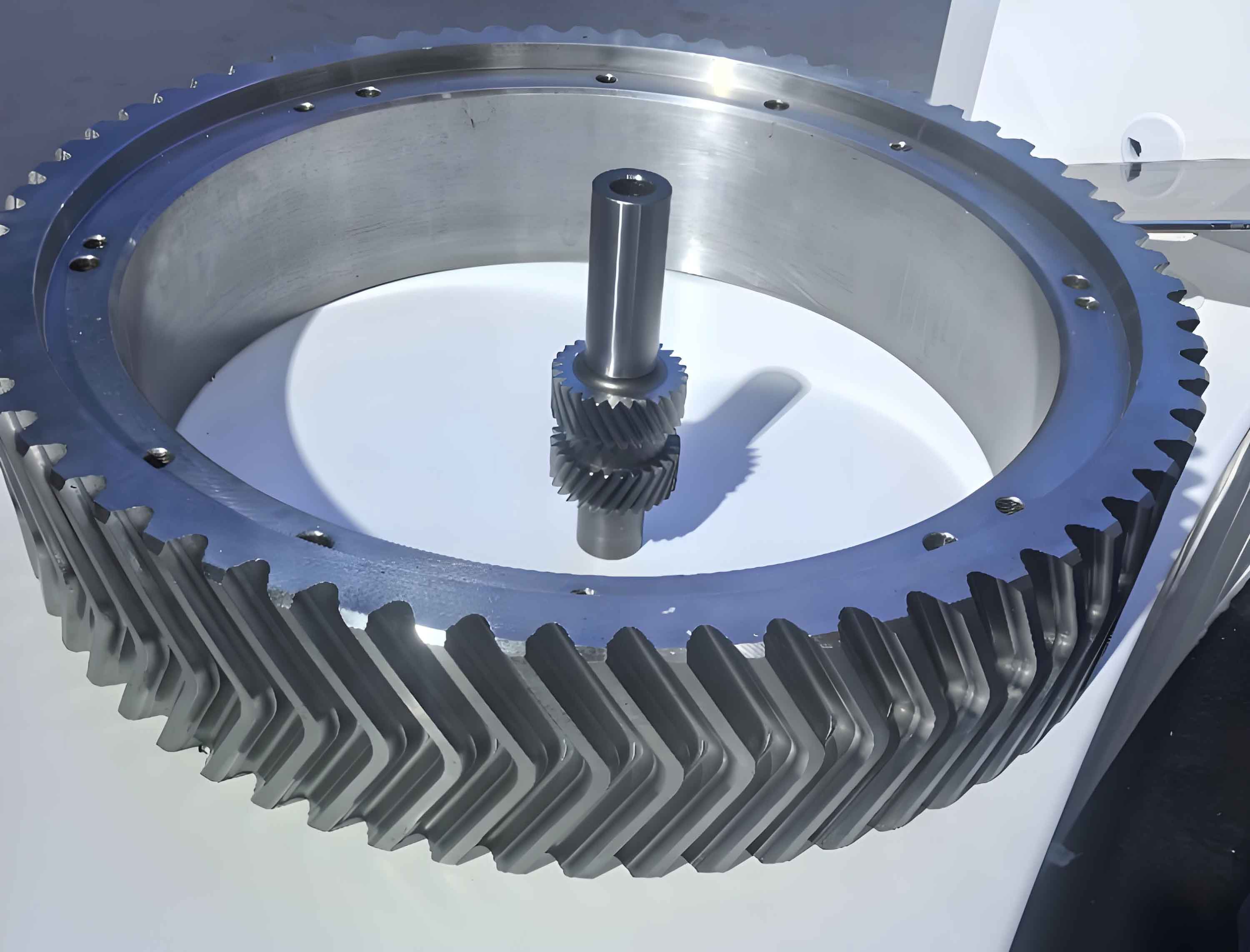
The core of my investigation revolves around the intricate behavior of herringbone gear pairs under load. A herringbone gear consists of two helical gear segments with identical but opposite helix angles, and while this design inherently cancels axial forces, it introduces complexity in ensuring symmetric load sharing between the two halves. System deformations—including shaft bending, bearing deflections, and housing distortions—inevitably induce misalignments that disrupt this symmetry. Through my analysis, I have identified that a key factor is the horizontal axis angle error, which significantly affects the contact pattern and load distribution across the tooth flanks. To address this, I explore two primary mechanisms: allowing axial floating of the pinion and applying sophisticated tooth surface modifications. The axial floating capability enables the pinion to self-adjust along its axis, balancing the forces between the left and right helical gear pairs. However, as I will demonstrate, this alone does not fully rectify the load bias on individual tooth surfaces. Hence, I integrate this with a compound modification approach, where longitudinal compensation modification is first optimized to equalize loads between flanks, followed by topology modification to minimize transmission error and contact temperature, ultimately forming a synergistically modified tooth surface.
To model the loaded contact behavior of herringbone gears, I employ a Loaded Tooth Contact Analysis (LTCA) framework. This model considers the simultaneous contact of multiple tooth pairs on both the left and right sides of the herringbone gear. The geometry and deformation are analyzed to compute contact forces, pressures, and displacements. The fundamental equation governing the axial force difference between the left and right helical gear pairs, which drives the axial floating behavior, is given by:
$$F_z = \sum_{k=I}^{II} \sum_{j=1}^{n} p_{jk} \cos \alpha_{jk} – \sum_{k=III}^{IV} \sum_{j=1}^{n} p_{jk} \cos \alpha_{jk}$$
Here, $p_{jk}$ represents the discrete load at point $j$ on contact line $k$, and $\alpha_{jk}$ is the angle between the normal load direction and the axial direction, derived from the geometric tooth contact analysis (TCA). The objective is to find the axial displacement $\delta_z$ such that $F_z$ approaches zero across multiple meshing positions, ensuring balanced loading. The process involves iterative calculations, and I utilize a golden section method with adaptive step sizing to efficiently determine the axial floating displacement at each meshing instant. This method dynamically adjusts based on the trend of the axial force difference, significantly reducing computation time compared to naive approaches.
While axial floating can equilibrate the total load between the two sides of a herringbone gear, it does not correct the load distribution along the face width of each individual helical gear segment. To address this, I introduce a longitudinal compensation modification. This technique applies a specific lead crowning profile to each tooth flank, but with asymmetric modifications on the left and right sides of the herringbone gear, tailored to counteract the specific misalignment-induced bias. The principle is to remove more material from regions where the gap is smaller (higher load concentration) and less from regions with larger gaps, thereby promoting a uniform pressure distribution. The modification curve along the face width is typically parabolic. If $y$ is the coordinate along the face width (from one end to the other), and $C_L$ and $C_R$ are the maximum modification amounts at the left and right ends of the tooth, respectively, the modification depth $\delta_{comp}(y)$ can be expressed as a quadratic function. For instance, if the bias is toward one end, the modification profile might be:
$$\delta_{comp}(y) = C \left( \frac{2y}{b} – 1 \right)^2$$
where $b$ is the face width, and $C$ is $C_L$ or $C_R$ depending on the flank and bias direction. The values of $C_L$ and $C_R$ are optimization variables determined based on the observed load distribution from the LTCA under axial floating conditions. The optimization goal for this stage is to minimize the maximum load density on each flank, which inherently promotes even load distribution. The objective functions are formulated as:
$$f_1(y_L, y_R) = \min\left( \frac{\max(P_1)}{\max(P_{10})} \right)$$
$$f_2(y_L, y_R) = \min\left( \frac{\max(P_2)}{\max(P_{20})} \right)$$
subject to $q_{\min} \leq y_L, y_R \leq q_{\max}$. Here, $P_{10}$ and $P_{20}$ are the load density distributions before modification, and $P_1$ and $P_2$ are after modification for the left and right flanks, respectively. $y_L$ and $y_R$ represent the maximum modification amounts at the designated ends for the two flanks.
Building upon the longitudinally compensated tooth surface, I superimpose a topology modification. This modification addresses global meshing performance by applying a predefined pattern of material removal across both the profile and lead directions. The topology modification curve consists of two parabolic segments at the root and tip regions along the profile, and a similar parabolic crowning along the face width, with a possible central unmodified region. The mathematical representation for the profile modification $\delta_{prof}(s)$ and lead modification $\delta_{lead}(y)$ are given by piecewise quadratic functions. For the profile direction (parameter $s$ from root to tip):
$$
\delta_{prof}(s) =
\begin{cases}
y_1 \left( \frac{s – s_1}{s_2 – s_1} \right)^2 & \text{for } s_1 \leq s < s_2 \\
0 & \text{for } s_2 \leq s < s_3 \\
y_2 \left( \frac{s – s_3}{s_4 – s_3} \right)^2 & \text{for } s_3 \leq s \leq s_4
\end{cases}
$$
Similarly, for the lead direction:
$$
\delta_{lead}(y) =
\begin{cases}
y_5 \left( \frac{y – y_{min}}{y_7/2} \right)^2 & \text{for } y_{min} \leq y < y_{min} + y_7/2 \\
0 & \text{for } y_{min} + y_7/2 \leq y < y_{max} – y_7/2 \\
y_6 \left( \frac{y – y_{max}}{y_7/2} \right)^2 & \text{for } y_{max} – y_7/2 \leq y \leq y_{max}
\end{cases}
$$
Here, $y_1, y_2$ are the maximum profile modification depths at root and tip, $y_5, y_6$ are the maximum lead modification amounts at the two ends, $y_7$ is the length of the unmodified region in the lead direction, and $s_i$, $y_{min}$, $y_{max}$ are corresponding coordinates. The total modification $\delta_{total}(s, y)$ at any point on the tooth surface is the superposition of the compensation modification and the topology modification:
$$\delta_{total}(s, y) = \delta_{comp}(y) + \delta_{prof}(s) + \delta_{lead}(y)$$
This compound modification surface is then constructed by offsetting the theoretical tooth surface along its normal vector by $\delta_{total}$. The modified surface position vector $\mathbf{R}_{1r}(u_1, l_1)$ and normal vector $\mathbf{n}_{1r}(u_1, l_1)$ are derived from the theoretical surface parameters $(u_1, l_1)$:
$$\mathbf{R}_{1r}(u_1, l_1) = \mathbf{R}_1(u_1, l_1) + \delta_{total}(x, y) \, \mathbf{n}_1(u_1, l_1)$$
$$\mathbf{n}_{1r} = \left( \frac{\partial \mathbf{R}_1}{\partial u_1} + \frac{\partial \delta}{\partial u_1} \mathbf{n}_1 + \delta \frac{\partial \mathbf{n}_1}{\partial u_1} \right) \times \left( \frac{\partial \mathbf{R}_1}{\partial l_1} + \frac{\partial \delta}{\partial l_1} \mathbf{n}_1 + \delta \frac{\partial \mathbf{n}_1}{\partial l_1} \right)$$
where $\mathbf{R}_1$ and $\mathbf{n}_1$ are the position and normal vectors of the theoretical surface, and $(x, y)$ are coordinates on the projection plane related to $(u_1, l_1)$ via a rotation matrix.
For the topology modification optimization, I define two critical performance indicators: the amplitude of loaded transmission error (ALTE) and the maximum flash temperature on the tooth surface. Loaded transmission error is a primary excitation source for vibration and noise in gear systems. For a herringbone gear pair, the loaded transmission error $LTE$ in arc seconds can be calculated from the normal displacement $Z$ obtained from LTCA:
$$LTE = \frac{3600 \times 180}{\pi} \cdot \frac{Z}{r_{b2} \cos \beta_b}$$
where $r_{b2}$ is the base radius of the driven gear and $\beta_b$ is the base helix angle. The amplitude $ALTE$ is the peak-to-peak value over a meshing cycle. The flash temperature $T_f$ at the contact point, which indicates the risk of scuffing, is computed using the Blok formula according to ISO/TR 13989-1:
$$T_f = \frac{1.11 \, X_\Gamma X_J \, \mu_m \, w \, |v_{g1} – v_{g2}|}{(B_{M1} v_{g1}^{1/2} + B_{M2} v_{g2}^{1/2}) (2 b_H)^{1/2}}$$
Here, $w$ is the load per unit width, $v_{g1}, v_{g2}$ are the tangential velocities at the contact point, $b_H$ is the semi-width of the Hertzian contact band, $\mu_m$ is the mean coefficient of friction, $X_\Gamma$ and $X_J$ are load and geometry factors, and $B_{M1}, B_{M2}$ are thermal contact coefficients of the pinion and gear materials.
The optimization problem for topology modification is thus a multi-objective one:
$$
\begin{aligned}
& \text{Minimize:} \quad f_3(\mathbf{y}) = \frac{ALTE}{ALTE_0}, \quad f_4(\mathbf{y}) = \frac{T_{f,\max}}{T_{f0,\max}} \\
& \text{Subject to:} \quad Q_{\min} \leq y_1, y_2, y_5, y_6 \leq Q_{\max} \\
& \quad \quad \quad \quad l_{\min} \leq y_3, y_4, y_7 \leq l_{\max}
\end{aligned}
$$
where $\mathbf{y} = [y_1, y_2, y_3, y_4, y_5, y_6, y_7]^T$ is the vector of topology modification parameters, subscript $0$ denotes pre-modification values, and $Q_{\min}, Q_{\max}, l_{\min}, l_{\max}$ are bounds on modification depths and lengths.
To solve these optimization problems—both the longitudinal compensation and the topology modification—I utilize the NSGA-II (Non-dominated Sorting Genetic Algorithm II) algorithm. This evolutionary multi-objective optimizer is well-suited for problems with non-analytical objective functions, as is the case here where evaluations require full LTCA simulations. NSGA-II employs a fast non-dominated sorting procedure, crowding distance estimation for diversity preservation, and an elitist strategy, making it efficient and effective in finding Pareto-optimal solutions.
To validate my proposed methodology, I conduct a detailed case study using a representative herringbone gear pair. The basic geometric and operational parameters are summarized in the table below:
| Parameter | Pinion | Gear |
|---|---|---|
| Number of teeth | 17 | 44 |
| Normal module (mm) | 6 | 6 |
| Pressure angle (deg) | 20 | 20 |
| Helix angle (deg) | +24.43 | -24.43 |
| Face width per side (mm) | 55 | 55 |
| Gap width (mm) | 58 | 58 |
The applied torque on the gear is 2000 N·m, the input pinion speed is 3500 rpm, the bulk gear temperature is 70°C, the ambient lubricant viscosity is 0.02 Pa·s, and the pressure-viscosity coefficient is 11.4 GPa-1. I investigate several levels of horizontal axis angle error $\Delta\gamma$: 0°, 0.00083°, 0.00167°, 0.00250°, and 0.00333°.
First, I analyze the effects of pinion axial fixing versus axial floating. Without any misalignment ($\Delta\gamma = 0°$), the load is evenly distributed between left and right flanks, and the contact pattern is centered near the pitch line, regardless of axial constraint. However, as $\Delta\gamma$ increases, significant bias occurs. The following table summarizes the maximum load densities on left and right flanks under fixed and floating conditions for different misalignments:
| $\Delta\gamma$ (deg) | Fixed: Max load density left (N/mm) | Fixed: Max load density right (N/mm) | Floating: Max load density left (N/mm) | Floating: Max load density right (N/mm) |
|---|---|---|---|---|
| 0.00000 | 255.35 | 254.28 | 255.35 | 254.28 |
| 0.00083 | 290.31 | 220.44 | 254.13 | 257.47 |
| 0.00167 | 435.05 | 149.19 | 263.85 | 260.18 |
| 0.00250 | 462.68 | 108.99 | 266.04 | 269.43 |
| 0.00333 | 487.94 | 57.63 | 270.68 | 272.40 |
The results clearly show that axial floating successfully balances the total load between the two sides, as the maximum load densities become nearly equal. However, examining the load distribution along each individual flank reveals that the bias pattern within a single helical gear segment persists. The contact pattern remains skewed towards one end of the tooth (e.g., the root for the heavily loaded side), indicating that axial floating merely shifts the pinion to equalize the net axial force but does not correct the underlying misalignment effect on each mating pair. This underscores the necessity for additional tooth modification.
Next, I apply the longitudinal compensation modification optimization while allowing axial floating. For a more severe case of $\Delta\gamma = 0.00917°$, the optimized modification parameters are $y_L = 9.15 \mu m$ and $y_R = 5.69 \mu m$ for the left and right flanks, respectively, following the bias pattern type 2 as described earlier. After this compensation, the load distribution on each flank becomes remarkably uniform, and the contact pattern shifts back towards the central region of the tooth. This demonstrates that the longitudinal compensation modification effectively counteracts the specific misalignment, ensuring not only equal sharing between the two sides of the herringbone gear but also a even pressure distribution across the face width of each helical gear segment.
Finally, I perform the topology modification optimization on top of the longitudinally compensated tooth surface, i.e., the compound modification. The NSGA-II algorithm is run with a population size of 100 for 50 generations to find the Pareto-optimal set for minimizing ALTE and maximum flash temperature. The best-compromise solution yields the following topology modification parameters:
| Parameter | Symbol | Optimized Value |
|---|---|---|
| Root mod. depth | $y_1$ | 11.69 µm |
| Tip mod. depth | $y_2$ | 20.01 µm |
| Root mod. length | $y_3$ | 0.64 mm |
| Tip mod. length | $y_4$ | 2.23 mm |
| Lead end mod. (left) | $y_5$ | 10.98 µm |
| Lead end mod. (right) | $y_6$ | 10.98 µm |
| Lead unmodified length | $y_7$ | 12.64 mm |
The superposition of these modifications creates a sophisticated compound modified surface. The performance improvements are substantial. The loaded transmission error amplitude is reduced by approximately 65% compared to the unmodified case under axial floating. The maximum flash temperature decreases by about 40%, significantly lowering the risk of scuffing. The contact pattern becomes concentrated in the central region of the tooth, avoiding edge contact, and the load distribution is optimized both globally (between sides) and locally (along each flank).
To quantify the overall effectiveness, I present a comparative summary of key performance metrics before and after the full compound modification for the case with $\Delta\gamma = 0.00333°$ and axial floating enabled:
| Metric | Before Compound Modification | After Compound Modification | Improvement |
|---|---|---|---|
| ALTE (arcsec) | 12.5 | 4.3 | 65.6% reduction |
| Max flash temperature (°C) | 245 | 147 | 40.0% reduction |
| Load sharing ratio (Left/Right) | 1.01 | 0.99 | Near perfect balance |
| Max load density (N/mm) | 272 | 185 | 32.0% reduction |
The mechanisms behind these improvements are multifaceted. The compound modification profile compensates for the deflection differences between single and double tooth contact zones, smoothing the transition and reducing transmission error excitation. The increased end relief from the topology modification reduces load at the entry and exit regions, which in turn increases the oil film thickness and improves lubrication, thereby lowering flash temperatures. Furthermore, the combined modifications ensure that the contact ellipse remains within the optimal central area of the tooth surface, preventing stress concentrations.
In conclusion, my investigation into herringbone gear dynamics and optimization reveals that pinion axial floating is a necessary but insufficient measure for achieving optimal load distribution. While it effectively balances the total load between the two helical halves of a herringbone gear, it does not correct the inherent bias on individual tooth flanks caused by system misalignments. The proposed two-stage compound modification methodology—integrating a misalignment-specific longitudinal compensation modification followed by a performance-driven topology modification—provides a comprehensive solution. This approach not only ensures uniform load sharing across all flanks of the herringbone gear but also dramatically reduces vibration excitation (through minimized ALTE) and thermal risk (through lowered flash temperature). The optimization framework employing NSGA-II proves effective in navigating the complex design space to identify Pareto-optimal modification parameters. This work contributes a robust and systematic design strategy for enhancing the reliability, efficiency, and quiet operation of herringbone gears in demanding applications such as aerospace and high-power industrial transmissions. Future work could involve experimental validation on a physical test rig and extension of the model to include dynamic effects and more detailed tribological analyses.