
In modern manufacturing, the gear milling process is a critical operation for producing precision components such as band saw blades. The efficiency and accuracy of gear milling directly impact product quality, tool life, and production costs. Traditional approaches to gear milling for band saw blades often rely on empirical three-stage feed rate strategies, which may not align with the dynamic cutting conditions during the milling process. This mismatch can lead to suboptimal surface finish, excessive tool wear, and reduced productivity. In this study, we aim to address these issues by developing a comprehensive model for calculating cutting volume during gear milling and proposing optimized process parameters based on the analysis.
The gear milling of band saw blades typically involves the use of form milling cutters with multiple cutting edges to shape the teeth and gullets. The process is characterized by complex interactions between the cutter geometry, workpiece material, and machining kinematics. Understanding the cutting volume distribution across the cutting edges is essential for optimizing feed rates and minimizing defects. However, due to the irregular shape of the cutter edges and the varying engagement lengths during milling, conventional cutting volume calculations are often inadequate. This research focuses on discretizing the cutting edge profile to establish a relationship between the depth of cut and the active edge length, enabling precise modeling of cutting volume for a single cutting edge in gear milling.
The gear milling process for band saw blades can be divided into three distinct phases: cutter entry, tooth formation, and cutter exit. Each phase involves different cutting conditions and requires tailored feed rates to balance efficiency and precision. In the cutter entry phase, the milling cutter initially contacts the bimetal strip, and the cutting volume gradually increases as the cutter penetrates the material. The tooth formation phase occurs when the cutting edges are fully engaged, and the saw teeth are shaped. Finally, in the cutter exit phase, the cutting edges disengage from the workpiece, and the cutting volume decreases. Traditional three-stage feed rate strategies often apply a slow-fast-faster sequence, which may lead to high cutting volumes during the critical tooth formation phase, adversely affecting accuracy. Our study seeks to refine this approach by analyzing cutting volume variations and proposing a multi-segment feed rate strategy.
To model the cutting volume in gear milling, we consider a single cutting edge of the form milling cutter. The cutting edge profile is discretized into small segments, allowing us to relate the depth of cut to the active edge length at any given moment. The kinematic motion of the cutter during gear milling is described using geometric and trigonometric relationships, accounting for the cutter rotation and linear feed motion. The cutting volume for a single edge is then calculated by integrating the product of the depth of cut and the active edge length over the engagement period. This model provides insights into how cutting volume changes throughout the gear milling process, enabling data-driven optimization.
We begin by defining the key parameters involved in gear milling. Let \( R \) be the radius of the milling cutter, \( h_1 \) be the distance from the cutter axis to the workpiece surface, and \( v_f \) be the feed rate in mm/min. The cutter rotates at an angular speed \( \omega \) in rpm. For a cutting edge numbered \( n \), we denote the angle at which it enters the workpiece as \( \alpha_n \) and the angle at which it exits as \( \beta_n \). The time interval between the engagement of consecutive edges is given by:
$$t_{n,n-1} = \frac{1}{n \omega}$$
The distance moved by the cutter axis in the feed direction during this interval is:
$$L_{n-1,n} = v_f t_{n,n-1}$$
The angular position of the cutter at time \( t \) is:
$$\alpha_t = 2\pi \omega t$$
Based on the geometry of the gear milling setup, the depth of cut \( a_{pn} \) for edge \( n \) can be expressed in three regimes corresponding to the phases of engagement. The general formula for \( a_{pn} \) is:
$$a_{pn} = \begin{cases} R – \frac{h_1}{\sin \alpha_t}, & \text{if } -\sin^{-1}\frac{h_1}{R} \geq \alpha_t \geq -\tan^{-1}\frac{h_1}{\sqrt{R^2 – h_1^2} – L_{n-1,n}} \\ R + L_{n-1,n} \cos \alpha_t – \sqrt{R^2 – L_{n-1,n}^2}, & \text{if } -\tan^{-1}\frac{h_1}{\sqrt{R^2 – h_1^2} – L_{n-1,n}} \geq \alpha_t \geq \tan^{-1}\frac{\sqrt{R^2 – x_{o,n-1}^2}}{x_{o,n-1}} \\ R – \frac{|x_{o,n}|}{\cos \alpha_t}, & \text{if } \tan^{-1}\frac{\sqrt{R^2 – x_{o,n-1}^2}}{x_{o,n-1}} \geq \alpha_t \geq \tan^{-1}\frac{|x_{o,n}|}{R} – \frac{\pi}{2} \end{cases}$$
Here, \( x_{o,n} \) represents the x-coordinate of the cutter axis when edge \( n \) is engaged. The depth of cut into the workpiece, denoted as \( L_{XntCnt} \), varies with the angular position and determines the active length of the cutting edge \( E_{XntCnt} \). For a given edge profile, the relationship between \( L_{XntCnt} \) and \( E_{XntCnt} \) can be derived through discretization. For example, for a tooth profile with a single transition fillet, common in band saw blades, this relationship is expressed as:
$$E_{XntCnt} = \begin{cases} 2R \cos^{-1}\left(\frac{R – L_{XntCnt}}{R}\right), & \text{if } R – R\cos J_2 \geq L_{XntCnt} \\ R \cos^{-1}\left(\frac{R – L_{XntCnt}}{R}\right) + R J_2 + \frac{L_{XntCnt} – R + R\cos J_2}{\sin J_2}, & \text{if } R + R\sin J_1 \geq L_{XntCnt} \geq R – R\cos J_2 \\ R\left(J_1 + J_2 + \frac{\pi}{2}\right) + \frac{L_{XntCnt} – R – R\cos J_2}{\sin J_2} + \frac{L_{XntCnt} – R – R\sin J_1}{\cos J_1}, & \text{if } H \geq L_{XntCnt} \geq R + R\sin J_1 \end{cases}$$
In this equation, \( H \) is the total tooth height, \( J_1 \) and \( J_2 \) are geometric angles defining the fillet and tooth shape, and \( R \) is the radius of the cutter edge curvature. The cutting area \( S_{at} \) at any instant is then:
$$S_{at} = E_{XntCnt} \cdot L_{XntCnt}$$
And the cutting volume \( V_n \) for edge \( n \) over its engagement period is:
$$V_n = \int_{-\sin^{-1}\frac{h_1}{R}}^{\alpha_{\text{exit}}} S_{at} \, d\alpha_t$$
This integral can be evaluated numerically for specific gear milling parameters. To illustrate the application of our model, we consider a typical band saw blade tooth profile with a single transition fillet. The parameters used in the simulation are summarized in Table 1.
| Parameter | Symbol | Value | Unit |
|---|---|---|---|
| Tooth Height | \( H \) | 3.58 | mm |
| Fillet Angle 1 | \( J_1 \) | 0.174 | rad |
| Fillet Angle 2 | \( J_2 \) | 0.54 | rad |
| Edge Curvature Radius | \( R \) | 2.64 | mm |
| Cutter Radius | \( R_c \) | 90 | mm |
| Feed Rate | \( v_f \) | 20 | mm/min |
| Rotational Speed | \( \omega \) | 80 | rpm |
| Workpiece Distance | \( h_1 \) | Variable | mm |
Using these parameters, we simulate the gear milling process and calculate the depth of cut and cutting volume for a single cutting edge. The results are shown in Figure 1, which plots the depth of cut against the cutter feed position. It is observed that the depth of cut is highest at the initial engagement point, reaching approximately 4.4 µm, and decreases as the cutter rotates, falling below 1 µm at exit. During the feed motion, the depth of cut remains relatively stable, indicating that a constant feed rate may not cause significant variations in cutting force due to depth changes. However, the cutting volume, which accounts for both depth and active edge length, shows more pronounced changes. Figure 2 illustrates the cutting volume variation across the feed positions. In the cutter entry phase, the cutting volume increases with feed; in the tooth formation phase, it remains constant; and in the cutter exit phase, it decreases.
These findings have important implications for optimizing the gear milling process. The traditional three-stage feed rate strategy, with a sequence of slow, fast, and faster feeds, may lead to excessive cutting volume during the tooth formation phase, where precision is critical. Instead, we propose a multi-segment feed rate strategy that adapts to the cutting volume variations. Specifically, the feed rate should follow a pattern of “fast – faster – slow – slower – fast – faster” across the gear milling cycle. This pattern is designed to reduce cutting volume during precision-sensitive phases while maintaining efficiency in other phases. For instance, in the initial cutter entry, a moderately fast feed can be used to improve efficiency without compromising tool integrity, as the cutting volume is low. As the cutter progresses, the feed should be increased further during the early entry phase to leverage the rising cutting volume for material removal. However, upon entering the tooth formation phase, the feed must be slowed down to minimize cutting volume and ensure accurate tooth geometry. During the later part of tooth formation, an even slower feed can be applied to further control cutting forces. In the cutter exit phase, where cutting volume declines, the feed can be accelerated again to boost productivity without sacrificing quality.
To implement this optimization, we recommend increasing the number of feed rate segments beyond three. By dividing the gear milling process into more segments, each with a tailored feed rate, we can better match the feed to the instantaneous cutting volume. This approach reduces fluctuations in cutting forces, minimizes tool vibration, and enhances surface finish. Additionally, controlling the depth of cut and cutting volume through adaptive feed rates can extend tool life by preventing overload during critical phases. The benefits of such optimization are particularly evident in high-precision applications like band saw blade manufacturing, where tooth geometry consistency is paramount.
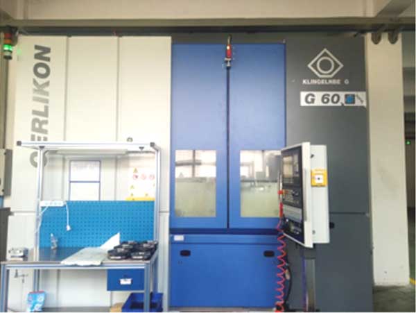
The gear milling machine depicted above exemplifies the advanced equipment used in such processes, highlighting the importance of precise control in modern manufacturing. Our model can be integrated into the machine’s CNC system to dynamically adjust feed rates based on real-time cutting volume calculations, enabling smarter and more efficient gear milling operations.
Further analysis of the gear milling process reveals that the cutting edge wear is influenced by the depth of cut and engagement length. The top of the cutting edge, which experiences the highest depth of cut and longest engagement time, is prone to accelerated wear. By optimizing feed rates to reduce cutting volume during peak engagement, we can distribute wear more evenly across the edge, prolonging tool life. This is especially relevant in gear milling for band saw blades, where the cutters have multiple edges and are subject to repetitive cycles.
To validate our model, we conducted additional simulations with varying parameters, such as different feed rates and cutter geometries. The results consistently show that cutting volume is a key determinant of machining performance. For example, increasing the feed rate during low-cutting-volume phases can reduce total machining time without increasing tool stress, while decreasing it during high-cutting-volume phases improves accuracy. Table 2 summarizes the recommended feed rate segments for an optimized gear milling process based on our simulations.
| Phase | Description | Recommended Feed Rate | Objective |
|---|---|---|---|
| Initial Entry | Cutter contacts workpiece | Fast (e.g., 25 mm/min) | Prevent vibration, start material removal |
| Early Entry | Cutting volume increases | Faster (e.g., 30 mm/min) | Maximize efficiency while volume is low |
| Tooth Formation Start | Cutting edges fully engaged | Slow (e.g., 15 mm/min) | Control cutting volume for precision |
| Tooth Formation Mid | Stable cutting volume | Slower (e.g., 10 mm/min) | Minimize forces for accurate geometry |
| Cutter Exit Start | Cutting volume decreases | Fast (e.g., 25 mm/min) | Accelerate as volume drops |
| Cutter Exit End | Final disengagement | Faster (e.g., 30 mm/min) | Boost productivity without quality loss |
This multi-segment strategy contrasts with the traditional three-stage approach, which often uses a fixed sequence that may not align with cutting volume trends. By incorporating cutting volume calculations into the gear milling process planning, manufacturers can achieve a better balance between speed and quality. Moreover, the model can be extended to other gear milling applications, such as gear hobbing or shaping, by adapting the edge profile discretization and kinematic equations.
In conclusion, our study demonstrates the importance of cutting volume modeling in optimizing the gear milling process for band saw blades. Through discretization of cutting edge profiles and kinematic analysis, we developed a model for calculating the depth of cut and cutting volume for a single cutting edge. Simulations using a typical tooth profile revealed that cutting volume varies significantly across the milling phases, with implications for feed rate selection. Based on these insights, we propose an optimized multi-segment feed rate strategy that adjusts feed rates according to cutting volume changes, aiming to improve efficiency and precision in gear milling. This approach not only addresses the limitations of traditional three-stage methods but also provides a framework for data-driven process optimization in gear milling and similar machining operations. Future work could focus on real-time implementation of the model using sensor data and machine learning algorithms for adaptive control, further enhancing the capabilities of gear milling in industrial applications.