
The manufacturing of high-performance gear shafts through forging presents a significant challenge due to the complex geometry of the gear teeth. Achieving complete die fill, especially in the tooth tip regions, often necessitates extremely high forging loads. These excessive loads not only demand larger, more expensive press equipment but also accelerate die wear and reduce overall tool life, negatively impacting the economic efficiency of the process. Therefore, a comprehensive evaluation of forging quality must extend beyond the final part’s integrity to include process parameters such as maximum forging load and its impact on die longevity.
A proven strategy to mitigate this issue is the implementation of splitter grooves (or overflow cavities) near difficult-to-fill areas. These grooves act as pressure relief zones and material reservoirs, guiding metal flow and significantly reducing the resistance during the final stages of filling the intricate tooth profiles. This study focuses on the analysis and optimization of splitter groove geometry for the extrusion forging of a specific gear shaft. Using numerical simulation, we investigate the influence of key splitter groove dimensions—depth, width, and transition angle—on the maximum forging load, which serves as a primary indicator for forging quality and process efficiency. The ultimate goal is to identify an optimal groove design that ensures complete filling of the gear shafts while minimizing the required press tonnage.
Geometry and Material of the Target Gear Shaft
The subject of this investigation is a transmission gear shaft. This component integrates gear teeth directly onto a shaft, a common design for compact power transmission systems. The shaft consists of three main sections: a left shaft section, a central gear section, and a right shaft section.
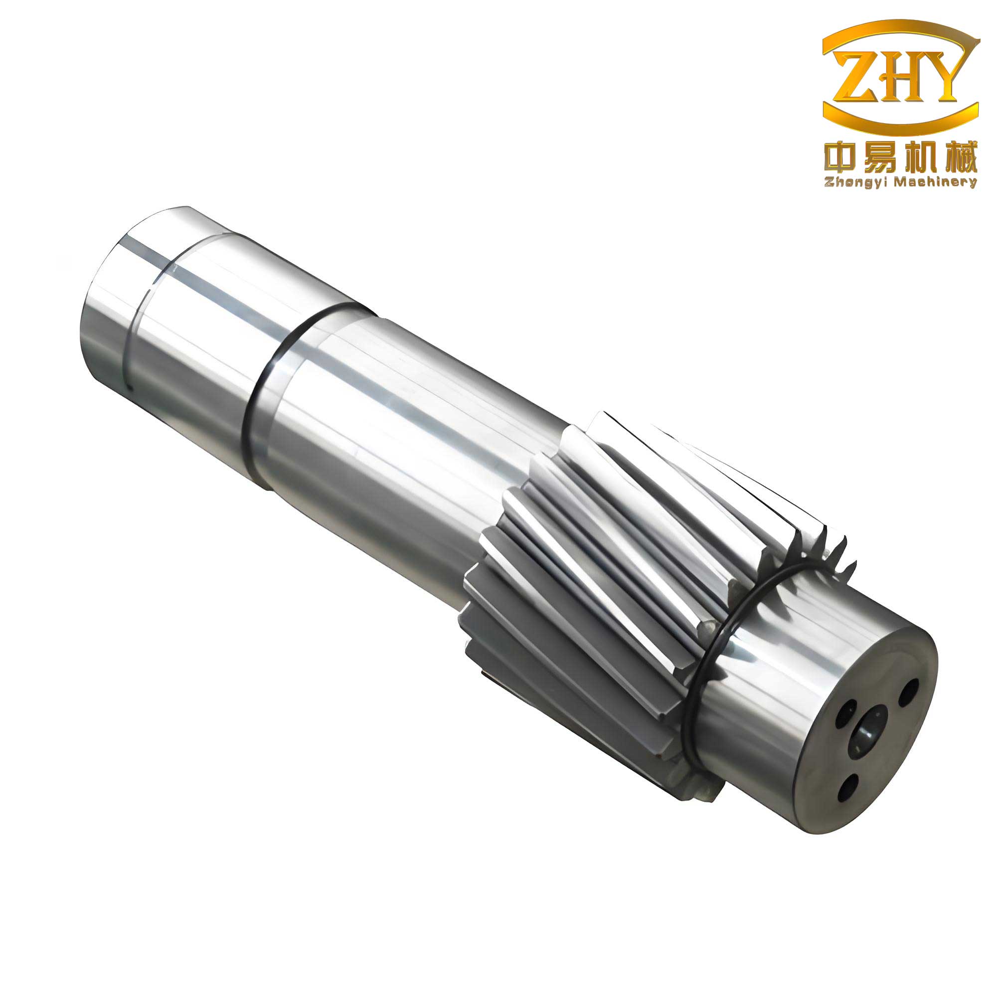
The left section has a length of 171 mm and a diameter of 52 mm. The right section is 68 mm long with a larger diameter of 78 mm. The central gear section has a face width of 46 mm. The gear specifications are as follows:
$$ \text{Module}, m = 7 \text{ mm}, \quad \text{Number of Teeth}, z = 18 $$
$$ \text{Pitch Circle Diameter}, D_p = m \times z = 126 \text{ mm} $$
$$ \text{Addendum Circle Diameter}, D_a = D_p + 2m = 140 \text{ mm} $$
$$ \text{Dedendum Circle Diameter}, D_d = D_p – 2.5m = 108.5 \text{ mm} $$
The material selected for these gear shafts is AISI 4140 steel (equivalent to 40Cr), a medium-carbon, low-alloy steel renowned for its high strength, good toughness, and excellent hardenability. Its superior hot workability and flow characteristics make it ideal for forging complex shapes like gear teeth. The key material properties for simulation are listed in Table 1.
| Property | Value | Unit |
|---|---|---|
| Elastic Modulus (at room temperature) | 210 | GPa |
| Tensile Strength (Yield) | ~990 | MPa |
| Density | 7.85 | g/cm³ |
| Poisson’s Ratio | 0.29 | – |
| Thermal Conductivity | ~42.6 | W/(m·K) |
Forging Process Setup and Die Design
The extrusion forging process for these gear shafts utilizes a closed-die system. The die assembly consists of five main components: a left punch, a left die, the central gear-shaped die insert (tooth die), a right die, and a right punch. The cylindrical billet is placed in the central cavity, and both punches move synchronously to extrude the material into the gear profile cavity.
The critical innovation in this die design is the incorporation of splitter grooves on the inner faces of both the left and right dies, adjacent to the gear die insert. These grooves are strategically positioned to receive excess material and facilitate flow into the challenging tooth tip regions during the final filling stage.
The geometry of the splitter groove, as shown in the schematic, is defined by two main segments: a Guide Segment and a Fill Segment.
- Guide Segment: This is the entry zone that connects the main die cavity to the fill segment. It features a curved surface (radius R1) transitioning into an angled plane. The primary parameter here is the Transition Angle (α).
- Fill Segment: This is the main reservoir with a rectangular cross-section. Its dimensions are defined by its Depth (H) and its Width (L1). The width of the guide segment’s opening is denoted as L2.
The relationship between these dimensions can be expressed as:
$$ L2 = L1 + 2H \cdot \cot(\alpha) $$
For the simulation, the following fixed process parameters were established:
- Billet Material: AISI 4140
- Billet Preheating Temperature: 900°C
- Die Material: AISI D3 (Cold Work Tool Steel)
- Die Preheating Temperature: 280°C
- Punch Speed: 6.5 mm/s
- Environment Temperature: 25°C
- Heat Transfer Coefficient (Die/Billet): 11 kW/(m²·K)
- Convection Coefficient (Die/Air): 20 W/(m²·K)
The radius of the curved guide (R1) was held constant at 10 mm. The variables for our study are therefore H, L1, and α.
Numerical Simulation Methodology
The analysis was conducted using a coupled thermo-mechanical finite element method (FEM). The three-dimensional models of the gear shaft and the die assembly were created using parametric CAD software. These models were then imported into a specialized metal forming simulation software (e.g., DEFORM-3D).
The simulation accounts for the complex interactions during forging:
- Plastic deformation and material flow of the gear shaft billet.
- Heat generation due to plastic work and friction.
- Heat transfer between the hot billet, the dies, and the environment.
- Die stress and calculation of forging load.
The flow stress of the AISI 4140 material is modeled as a function of strain, strain rate, and temperature, typically using an Arrhenius-type equation:
$$ \sigma = f(\epsilon, \dot{\epsilon}, T) $$
where \( \sigma \) is the flow stress, \( \epsilon \) is the strain, \( \dot{\epsilon} \) is the strain rate, and \( T \) is the temperature. The primary output metric for evaluating the influence of the splitter groove is the Maximum Forging Load (F_max) on the central gear die insert, recorded at the end of the stroke when the tooth cavities are completely filled.
Influence of Splitter Groove Dimensions on Forging Load
The systematic investigation involved varying one splitter groove parameter at a time while keeping the others constant, as per the baseline and the findings from subsequent optimizations.
Effect of Groove Depth (H)
The depth of the splitter groove was varied from 2.0 mm to 4.0 mm, with a constant width L1 = 6.5 mm and transition angle α = 40°. The resulting maximum forging load trend is shown in Figure 1 (conceptual description).
The load decreases significantly as H increases from 2.0 mm to approximately 2.7 mm. In this range, the deeper groove provides a more substantial volume for material to flow into, effectively reducing pressure build-up in front of the tooth tips. The rate of load reduction slows down between H = 2.7 mm and 3.3 mm. Beyond H = 3.3 mm, the curve plateaus, indicating that further increasing the depth yields no appreciable benefit in load reduction. The groove has reached a “saturation” depth where its capacity to relieve pressure is maximized for the given other parameters. Therefore, an optimal depth of H_opt = 3.3 mm is identified.
| Depth, H (mm) | Load Trend | Interpretation |
|---|---|---|
| 2.0 – 2.7 | Sharp Decrease | Increased volume significantly relieves pressure. |
| 2.7 – 3.3 | Gradual Decrease | Diminishing returns on volume increase. |
| > 3.3 | Plateau | Saturation effect; optimal depth reached. |
Effect of Groove Width (L1)
With the optimal depth fixed at H = 3.3 mm and α = 40°, the groove width L1 was varied from 6.0 mm to 13.0 mm. The relationship between forging load and groove width is shown in Figure 2 (conceptual description).
A rapid reduction in forging load is observed as L1 increases from 6.0 mm to about 8.5 mm. A wider opening (L1) directly increases the cross-sectional area through which material can enter the splitter, improving its efficiency as a pressure relief zone during the forging of the gear shafts. For widths greater than 8.5 mm, the load continues to decrease but at a much slower, almost negligible rate. This suggests that a width of approximately 8.5 mm is sufficient to fully realize the load-reduction potential for this specific gear shaft geometry. Thus, the optimal width is selected as L1_opt = 8.5 mm.
The load as a function of width can be approximated by a piecewise relationship:
$$
F_{\text{max}}(L1) \approx
\begin{cases}
F_0 – k_1(L1 – 6.0) & \text{for } 6.0 \leq L1 \leq 8.5 \\
F_{8.5} – k_2(L1 – 8.5) & \text{for } L1 > 8.5
\end{cases}
$$
where \( k_1 \gg k_2 \), indicating the high sensitivity in the initial range.
Effect of Transition Angle (α)
Finally, with H = 3.3 mm and L1 = 8.5 mm, the transition angle α was varied from 20° to 60°. The effect on forging load is non-monotonic and particularly interesting, as shown in Figure 3 (conceptual description).
As α increases from 20° to about 42°, the forging load drops steadily. A steeper transition angle (closer to vertical) creates a more direct path for material to enter the fill segment, reducing flow resistance. This facilitates easier filling of the splitter groove, which in turn helps lower the pressure required to fill the gear teeth of the gear shafts. The load remains at a stable, low minimum plateau for angles between approximately 42° and 52°. However, beyond 52°, the forging load increases sharply. Excessively large angles (e.g., 60°) essentially create an undercut or a near-vertical wall, which hinders the initial flow of material into the groove. This obstruction increases the forming pressure instead of relieving it. Consequently, an optimal range for the transition angle is identified as α_opt = 42° – 52°, with 42° chosen as the nominal value for the final design.
| Angle, α (degrees) | Load Trend | Interpretation |
|---|---|---|
| 20 – 42 | Decreasing | Improved material guidance into the groove. |
| 42 – 52 | Low Plateau | Optimal guidance with minimal resistance. |
| 52 – 60 | Sharp Increase | Undercut effect creates a flow barrier. |
Optimal Design Validation and Filling Analysis
Based on the parametric study, the optimal splitter groove geometry for forging this specific gear shaft is defined as:
$$ H_{\text{opt}} = 3.3 \text{ mm}, \quad L1_{\text{opt}} = 8.5 \text{ mm}, \quad \alpha_{\text{opt}} = 42^\circ $$
A final simulation was run with this optimized configuration to validate the filling quality. The analysis of the material flow sequence confirmed that the splitter grooves functioned as intended.
During the early and middle stages of forging, the material flows axially to form the shaft sections and radially to begin filling the gear teeth. In the final stage, when the tooth tips become the last areas to fill, the pressure rises. With the optimized splitter grooves, the material adjacent to the grooves finds an alternative path. It smoothly flows into the guide and fill segments of the groove, preventing a severe pressure spike. The simulation results showed complete and uniform filling of all gear teeth without any defects such as underfill or folds. Crucially, the maximum forging load recorded with this optimal design was approximately 25% lower compared to a baseline design with minimal or no splitter grooves.
The effectiveness \( \eta \) of the splitter groove in load reduction can be conceptualized as a function of its geometry and the specific stage of filling the gear shafts:
$$ \eta(H, L1, \alpha) \propto \frac{1}{F_{\text{max}}(H, L1, \alpha)} $$
The optimization process successfully maximized \( \eta \) for the given constraints.
Conclusion
This investigation underscores the critical importance of splitter groove design in the extrusion forging of complex components like gear shafts. Through detailed finite element analysis, the influence of key geometric parameters—depth (H), width (L1), and transition angle (α)—on the maximum forging load was quantitatively evaluated.
The results demonstrate that increasing the depth and width of the splitter groove generally improves material flow and reduces the required load, but only up to a point of saturation where further increases yield minimal benefit. The transition angle exhibits a more complex relationship, with an optimal range that provides efficient material guidance; angles outside this range, particularly overly large ones, can be detrimental by creating flow barriers.
For the studied gear shaft, the optimal splitter groove configuration was determined to be 3.3 mm in depth, 8.5 mm in width, and a 42° transition angle. This design ensures complete die fill of the challenging tooth profile while minimizing the forging load. This reduction in load directly translates to extended die life, reduced press capacity requirements, and lower operating costs, significantly enhancing the overall forging quality and economic viability of manufacturing these gear shafts. The methodology presented provides a valuable framework for the design and optimization of forging processes for other complex axisymmetric parts.