
In the realm of high-voltage power systems, disconnectors play a critical role in ensuring operational safety by isolating equipment from live circuits during maintenance or installation. Among these, the GW16/17 type disconnector is widely deployed due to its robust structural design, excellent electrical and mechanical performance, and enhanced resistance to corrosion and seismic events. A key component within this system is the bevel gear assembly, which facilitates torque transmission between the double four-bar linkage and the rotating porcelain insulator in the main knife base assembly. During the opening and closing operations of the disconnector, these bevel gears are subjected to significant loads and impacts, making them susceptible to failures such as pitting, fracture, and deformation. Therefore, a comprehensive analysis of their contact strength is essential for reliability assessment. In this article, I will delve into the theoretical calculations, three-dimensional modeling, and transient contact finite element analysis (FEA) of these bevel gears, aiming to validate their performance under operational conditions.
The bevel gear system in the GW16/17 disconnector employs a pair of spiral bevel gears to convert rotational motion, allowing an input rotation of 90 degrees to yield an output rotation of 180 degrees. This motion is further transmitted via linkages to actuate the main knife. The gears are typically manufactured from 40Cr steel, known for its high strength and toughness, with a Poisson’s ratio of 0.3, an elastic modulus of 210 GPa, and a density of 7.82 g/cm³. The maximum output torque from the electric operating mechanism is set at 1000 N·m for analysis purposes. To evaluate the contact strength, theoretical calculations are first performed based on standard gear design principles.
The circumferential force acting on the bevel gear can be expressed as:
$$F_t = \frac{T}{m Z_1 \phi_R}$$
where \( T \) is the input torque, \( m \) is the module of the bevel gear, \( Z_1 \) is the number of teeth on the pinion (small bevel gear), and \( \phi_R \) is the face width coefficient, typically taken as \( \phi_R = b / R \), with \( b \) as the face width and \( R \) as the cone distance. For this analysis, \( Z_1 = 18 \) and \( \phi_R \) is assumed to be 0.3 based on common design practices.
The contact stress at the pitch circle is calculated using the Hertzian contact theory adapted for bevel gears:
$$\sigma_H = Z_H Z_E Z_{\epsilon} Z_{\beta} \sqrt{ \frac{F_t}{b d_1} \cdot \frac{u+1}{u} \cdot K_A K_V K_{H\beta} K_{H\alpha} }$$
where \( Z_H \) is the zone factor, \( Z_E \) is the elasticity coefficient, \( Z_{\epsilon} \) is the contact ratio factor, \( Z_{\beta} \) is the spiral angle factor, \( K_A \) is the application factor, \( K_V \) is the dynamic factor, \( K_{H\beta} \) is the face load distribution factor, \( K_{H\alpha} \) is the transverse load distribution factor, \( b \) is the face width, \( u \) is the gear ratio (\( u = Z_2 / Z_1 \)), and \( d_1 \) is the pitch diameter of the pinion. The parameters are derived from mechanical design handbooks and operational conditions of the disconnector.
Table 1 summarizes the key stress parameters used in the calculation:
| Parameter | Symbol | Value |
|---|---|---|
| Module | \( m \) | 3 mm |
| Face Width | \( b \) | 20 mm |
| Gear Ratio | \( u \) | 2 |
| Zone Factor | \( Z_H \) | 2.5 |
| Elasticity Coefficient | \( Z_E \) | 189.8 √MPa |
| Contact Ratio Factor | \( Z_{\epsilon} \) | 0.85 |
| Spiral Angle Factor | \( Z_{\beta} \) | 0.95 |
| Application Factor | \( K_A \) | 1.25 |
| Dynamic Factor | \( K_V \) | 1.1 |
| Face Load Distribution Factor | \( K_{H\beta} \) | 1.15 |
| Transverse Load Distribution Factor | \( K_{H\alpha} \) | 1.05 |
Substituting these values into the equations, the circumferential force is computed as:
$$F_t = \frac{1000 \text{ N·m}}{3 \times 10^{-3} \text{ m} \times 18 \times 0.3} \approx 617.28 \text{ kN}$$
And the contact stress is:
$$\sigma_H = 2.5 \times 189.8 \times 0.85 \times 0.95 \times \sqrt{ \frac{617.28 \times 10^3}{20 \times 10^{-3} \times 54 \times 10^{-3}} \times \frac{2+1}{2} \times 1.25 \times 1.1 \times 1.15 \times 1.05 } \approx 211.71 \text{ MPa}$$
This theoretical value serves as a benchmark for subsequent finite element analysis of the bevel gear system.
To create an accurate digital representation, a three-dimensional model of the bevel gears is developed using SolidWorks software. The gears are positioned within the upper conductive base of the porcelain insulator assembly, where they transmit torque to achieve the required motion conversion. The modeling process begins with defining the geometric parameters of the spiral bevel gears, as listed in Table 2.
| Parameter | Pinion (Small Bevel Gear) | Gear (Large Bevel Gear) |
|---|---|---|
| Number of Teeth | 18 | 36 |
| Module | 3 mm | 3 mm |
| Pressure Angle | 20° | 20° |
| Spiral Angle | 35° | 35° |
| Face Width | 20 mm | 20 mm |
| Pitch Diameter | 54 mm | 108 mm |
| Cone Distance | 60 mm | 60 mm |
Using these parameters, I generate the solid models of both bevel gears, ensuring proper tooth profiles and alignment. The assembly is then constructed by mating the gears at a 90-degree intersection, simulating their actual configuration in the disconnector. To streamline the FEA process, the model is simplified by removing non-essential features such as fillets and minor bores that have negligible impact on stress distribution. The final assembly, showcasing the interacting bevel gears, is prepared for import into ANSYS.
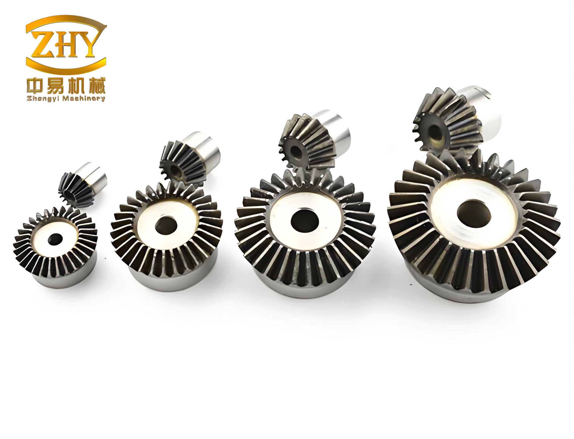
This image illustrates the typical appearance of bevel gears, similar to those used in the GW16/17 disconnector, highlighting their conical shape and tooth engagement.
For the transient contact finite element analysis, the simplified bevel gear model is imported into ANSYS Workbench via a seamless interface with SolidWorks. The analysis aims to simulate the dynamic loading conditions during disconnector operation, providing insights into stress evolution over time. The first step involves defining the element properties and material attributes. The bevel gears are assigned the properties of 40Cr steel: elastic modulus of 210 GPa, Poisson’s ratio of 0.3, and density of 7820 kg/m³. The contact between the gears is configured as frictional with a coefficient of 0.2, and an asymmetric behavior is selected to account for the geometric differences. Additionally, rotational connections are established to simulate the gears’ motion relative to ground, with the large bevel gear designated as the input driver.
Mesh generation is critical for accuracy. A mixed approach using hexahedral and tetrahedral elements is employed. The bevel gears are meshed with a sweep method, while the contact regions are locally refined to capture stress concentrations effectively. After meshing, the model comprises 707,868 nodes and 459,565 elements, as shown in the mesh diagram. This dense discretization ensures reliable results for the transient analysis.
Boundary conditions and loads are applied to mimic real-world scenarios. A torque of 1000 N·m is imposed on the large bevel gear, representing the maximum output from the operating mechanism. The support conditions are set as frictionless at the gear bores to allow free rotation. The analysis is set as transient, with a time step that covers several engagement cycles to observe stress variations during meshing.
Upon solving the finite element model, the results reveal the contact stress distribution on the bevel gears. The maximum von Mises stress obtained from the simulation is 222.72 MPa, which compares favorably with the theoretical value of 211.71 MPa. The relative error is approximately 5.2%, which is within acceptable engineering limits. This discrepancy can be attributed to several factors: the theoretical calculation assumes force application at the pitch circle, whereas in reality, the contact line shifts during meshing; simplifications in the FEA model, such as ignored dynamic effects like centrifugal forces; and approximations in mesh density and contact settings. Nevertheless, the close agreement validates the finite element approach for analyzing bevel gear contact strength.
To further assess the safety of the bevel gears under operational loads, a safety factor analysis is conducted based on the yield strength of 40Cr steel (typically around 785 MPa). The safety factor \( n \) is calculated as:
$$n = \frac{S_y}{\sigma_{max}}$$
where \( S_y \) is the yield strength and \( \sigma_{max} \) is the maximum stress from FEA. Using \( S_y = 785 \text{ MPa} \) and \( \sigma_{max} = 222.72 \text{ MPa} \), the safety factor is:
$$n = \frac{785}{222.72} \approx 3.52$$
This indicates a substantial margin of safety, well above the minimum requirement of 1.0. However, for more precise evaluation, the FEA software directly computes the safety factor distribution across the gear teeth, showing a minimum value of 1.0387 in the highest-stress regions. This confirms that the bevel gears will not reach yield under normal operating conditions, ensuring long-term reliability.
The transient analysis also provides insights into stress fluctuations during gear engagement. The contact stress peaks at the initial contact point and diminishes as the teeth roll through mesh, aligning with expected behavior for spiral bevel gears. This dynamic perspective helps identify potential fatigue initiation sites, which are crucial for predicting service life. Moreover, the analysis underscores the importance of proper lubrication and alignment in reducing stress concentrations, topics that warrant further investigation.
In conclusion, the combination of theoretical calculations and finite element analysis offers a robust framework for evaluating the contact strength of bevel gears in high-voltage disconnectors. The theoretical contact stress of 211.71 MPa and the FEA result of 222.72 MPa show good consistency, with an error of about 5.2%, demonstrating the reliability of simulation tools for such applications. The safety factor analysis further affirms that the bevel gears in the GW16/17 disconnector are adequately designed to withstand operational loads without yielding. This work highlights the value of integrated analytical approaches in engineering design, particularly for critical components like bevel gears that endure cyclic loading. Future studies could explore the effects of wear, thermal gradients, and material imperfections on gear performance, leveraging advanced FEA techniques to enhance predictive accuracy. Ultimately, understanding the behavior of bevel gears through methods like transient contact analysis contributes to safer and more efficient power grid operations.