
The manufacturing of spur gears is a continuous production process where precision forging must balance efficiency with die reliability. With the advancement of cold extrusion technology, this net-shape or near-net-shape manufacturing method is increasingly employed for producing spur gears. Gears formed through cold extrusion exhibit smooth tooth surfaces, continuous metal flow lines, and high load-bearing capacity, making them a preferred choice for many applications. However, the widespread adoption of cold extrusion has traditionally been limited to small-modulus, narrow-face-width spur gears due to challenges with post-extrusion accuracy stability and limited die service life. The development of combined “cold extrusion + cold precision sizing” processes and the application of new high-strength, high-hardness carbide materials are now enabling this advanced forming route to replace traditional machining for high-modulus spur gears. The key to successful precision plastic forming of such gears lies in ensuring final part accuracy. This article investigates the critical influence of the sizing method itself on the final quality of high-modulus spur gears.
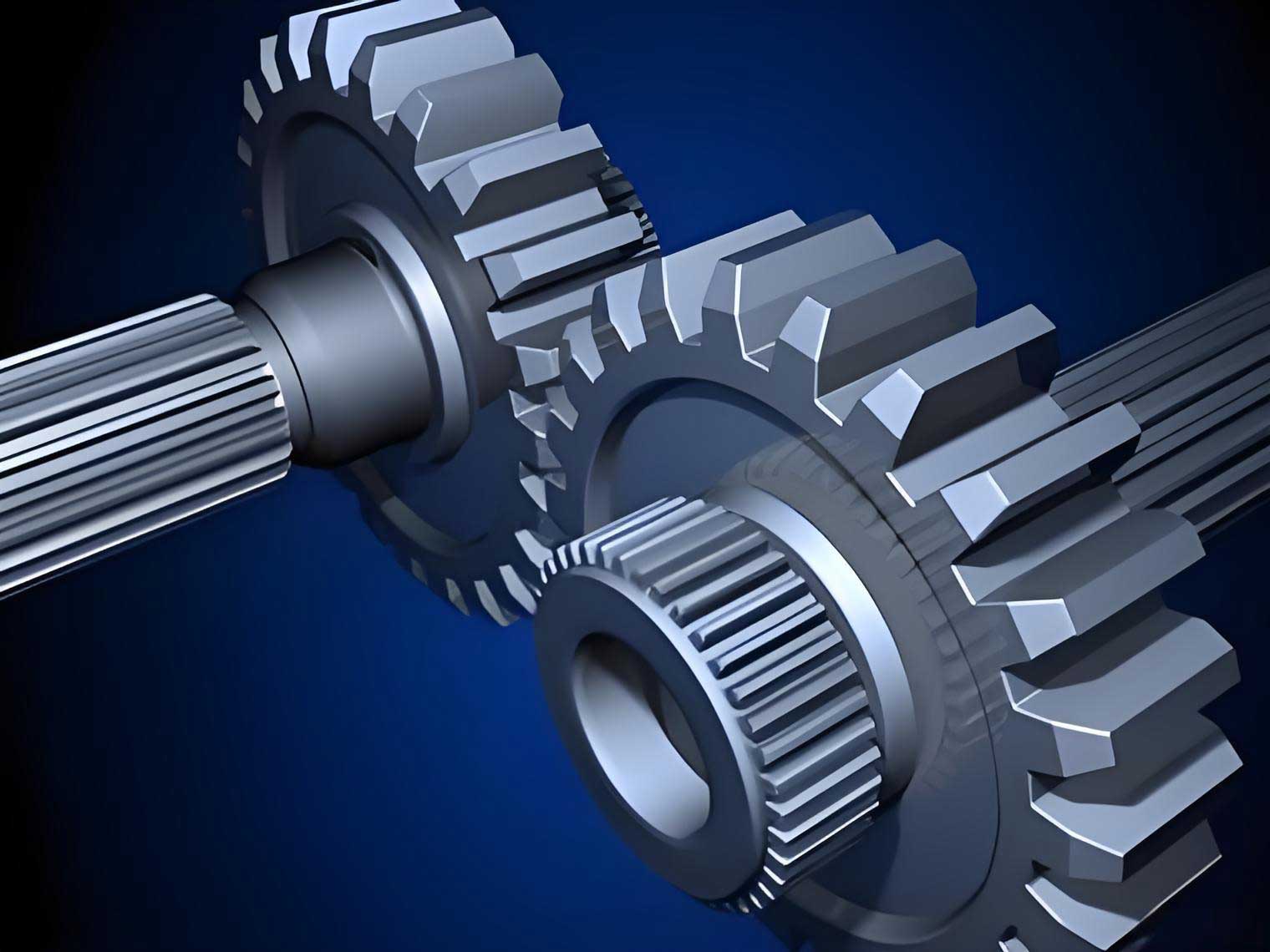
Spur gears are fundamental power transmission components. Recent research has focused heavily on improving the accuracy of formed spur gears. Studies have examined size deviation changes during sizing, optimized sizing allowances for large-modulus spur gears, and analyzed the influence of sizing allowance magnitude and multiple sizing passes on form accuracy. Other work has investigated surface roughness, dimensional changes after two-pass sizing, and the causes of barrel-shaped tooth profiles post-sizing. The influence of solid versus hollow billets on gear forming quality has also been explored. A common thread in much of this prior numerical and experimental work is the use of ideal, error-free gear models. This approach does not accurately reflect the actual condition of a cold-extruded spur gear entering the sizing operation, which inherently possesses dimensional errors. Furthermore, most studies default to a full-tooth sizing strategy without critically comparing the effects of different sizing methodologies on final spur gear accuracy, die stress, and process robustness. This work addresses these gaps by employing a measured, non-ideal spur gear model to simulate and experimentally validate different cold precision sizing strategies for a high-modulus spur gear.
Process Analysis and Sizing Allowance Determination for Spur Gears
Process Scheme for High-Modulus Spur Gears
The subject of this study is a high-modulus spur gear used in a heavy-duty vehicle wheel-edge reducer. Its key parameters are: module \\( m = 4 \\), number of teeth \\( Z = 16 \\), pressure angle \\( \\alpha = 20^{\\circ} \\), and profile shift coefficient \\( x = 0.45 \\). The required tooth flank accuracy is high, with both tooth profile and helix direction accuracies required to meet ISO Grade 8 per GB/T 10095-2001. The forming process sequence is: hot forging for preform → spheroidizing anneal → shot blasting → turning → phosphating & soaping → cold extrusion → cold precision sizing. The material is 20CrMnTi alloy steel. Initial measurement of the cold-extruded spur gears revealed an accuracy of only ISO Grade 10, necessitating the cold precision sizing operation to meet design specifications. During sizing, the workpiece is pushed continuously through a sizing die. The extruded spur gears typically exhibit flash or fold-overs of approximately 2 mm at both axial ends. To ensure full tooth form, the extrusion die is often modified. Consequently, the primary goal of sizing for these high-modulus spur gears is to refine the tooth flanks, as the tooth root accuracy from extrusion is usually sufficient.
Methods of Cold Precision Sizing
Based on the accuracy requirements, three distinct cold precision sizing strategies were designed for the spur gear, as conceptually illustrated below:
- Full-Tooth Sizing: The entire tooth profile, including tip, flank, and root, is subjected to the sizing operation.
- Flank-and-Root Sizing: Only the tooth flank and root regions are sized. The tooth tip is later finished by turning.
- Flank-Only Sizing: Only the active tooth flank is sized. The sizing die is deliberately relieved (given clearance) in the tooth tip and root regions.
Calculation of the Sizing Allowance
The sizing allowance is a paramount parameter in cold precision sizing, directly influencing the final accuracy of the spur gear. Based on analysis of deformation in a cylindrical model analogous to a gear tooth, the total single-side sizing allowance \\( \\Delta L \\) can be derived as the sum of three primary components:
$$ \Delta L = L_1 + L_2 + L_3 $$
Where:
- \\( L_1 \\) = Single-side plastic deformation of the tooth profile.
- \\( L_2 \\) = Single-side elastic deformation of the sizing die.
- \\( L_3 \\) = Single-side elastic springback of the spur gear after sizing.
The plastic deformation component \\( L_1 \\) is often empirically set based on desired dimensional change and material flow, typically on the order of 0.10 mm or similar. The die elastic deformation \\( L_2 \\) can be estimated considering the die as a thick-walled cylinder under internal pressure:
$$ L_2 = L_s \\left( e^{\\sigma / E} – 1 \\right) $$
Where \\( L_s \\) is the die dimension before elastic deflection, \\( \\sigma \\) is the internal pressure on the die, and \\( E \\) is the elastic modulus of the die material. The springback of the spur gear \\( L_3 \\) depends on the relieved elastic strain \\( \\epsilon \\) and the gear geometry:
$$ L_3 = \\left( \\frac{m \\pi}{2} + 2 m x \\tan \\alpha \\right) (1 – e^{-\\epsilon}) $$
For the specific spur gear in this study, applying these formulas and rounding the result yielded a recommended single-side sizing allowance of 0.15 mm. This value was consequently used as the standard for both numerical simulation and process experiments.
Numerical Simulation and Comparative Analysis of Spur Gear Sizing
Establishment of the Finite Element Model
To closely mimic reality, the finite element model was constructed using actual measurement data from a cold-extruded spur gear, rather than an ideal, zero-error model. Measurements using a gear tooth caliper showed that the tooth thickness at the center of the face width was approximately 0.03 mm less than at the ends, indicating a non-uniform extrusion. This measured geometry was used to create three separate 3D finite element models, one for each sizing strategy. To reduce computational cost, a single-tooth sector model was employed. The spur gear blank was defined as an elastic-plastic body with material properties of 20CrMnTi. The sizing die was modeled as a rigid body, neglecting its elastic deformation and thermal effects for simplification. The spur gear mesh was composed of hexahedral elements, with local refinement in the tooth profile region. Key simulation parameters are summarized in Table 1.
| Parameter | Value/Type |
|---|---|
| Number of Elements | 44,820 |
| Friction Type | Shear |
| Friction Coefficient | 0.08 |
| Temperature | 20 °C |
| Pushing Speed | 10 mm/s |
After simulation, a point-tracking method was used to extract the coordinates of all nodes on the sized tooth flank. This data was imported into CAD software to reconstruct the surface, allowing for virtual measurement of the tooth profile total deviation \\( F_{\\alpha} \\) and the helix total deviation \\( F_{\\beta} \\)—the two critical accuracy metrics for spur gears.
Deformation Behavior Under Different Sizing Methods
The effective stress distribution within the spur gear tooth differed significantly between methods. In Full-Tooth Sizing, the entire tooth volume experienced high stress. In Flank-and-Root Sizing, although the tip had no direct sizing allowance, metal flow from the flank caused secondary deformation at the tip. In Flank-Only Sizing, plastic deformation was concentrated almost exclusively on the flank, with excess material flowing freely into the relieved tip area.
The effective strain distribution further highlighted these differences. In both Full-Tooth and Flank-and-Root sizing, strain was less uniform along the tooth flank. The Flank-Only method resulted in the most uniform strain distribution across the active flank of the spur gear, which is desirable for consistent accuracy improvement.
The stress on the sizing die is a critical factor for die life. The maximum principal stress distributions revealed a crucial finding:
- Full-Tooth Sizing: The die tooth tip experienced very high compressive stress, approximately 1800 MPa.
- Flank-and-Root Sizing: The die tooth tip stress was even higher, around 2010 MPa, due to constrained metal flow.
- Flank-Only Sizing: With the tip relieved, the die tooth tip was not subjected to high stress. The contact stress on the die flank ranged from 700-1200 MPa, significantly lower than the peak stresses in the other methods.
This indicates that the Flank-Only Sizing strategy can dramatically reduce stress concentrations in the sizing die, potentially leading to a substantially longer service life for the expensive, precision-machined die used for producing spur gears.
Influence of Sizing Method on Spur Gear Accuracy
The reconstructed tooth surfaces from each simulation were analyzed for accuracy. The results, quantifying the improvements in the critical deviation parameters for the spur gear, are presented in Table 2.
| Cold Sizing Method | Tooth Profile Total Deviation \\( F_{\\alpha} \\) (mm) | Helix Total Deviation \\( F_{\\beta} \\) (mm) |
|---|---|---|
| Full-Tooth Sizing | 0.031 | 0.044 |
| Flank-and-Root Sizing | 0.024 | 0.035 |
| Flank-Only Sizing | 0.014 | 0.019 |
The Full-Tooth Sizing method yielded the largest deviations and thus the poorest accuracy improvement for the spur gear. This is attributed to the complex, constrained metal flow across the entire tooth profile, causing non-uniform plastic deformation that hinders precise form correction. The Flank-Only Sizing method, with its focused deformation zone and free material flow at the tip, achieved the most significant enhancement in the accuracy of the spur gear, reducing both profile and helix deviations to the lowest simulated values.
Process Experimentation and Validation
Based on the simulation findings—which favored Flank-Only Sizing for both spur gear accuracy and die stress reduction—this method was selected for physical process validation. The single-side sizing allowance was set to 0.15 mm. Experiments were conducted on a hydraulic press using a combined, prestressed sizing die with a Cr12MoV insert. The cold-extruded spur gears underwent phosphating and soaping treatment before sizing.
Five randomly selected spur gears were measured before and after sizing on a gear measuring center. For each gear, the left and right flanks of three teeth approximately equally spaced around the circumference were measured for \\( F_{\\alpha} \\) and \\( F_{\\beta} \\). A paired-sample t-test was performed on the collected data to determine the statistical significance of the accuracy improvement. Descriptive statistics for the paired samples are shown in Table 3.
| Parameter | Tooth Profile Total Deviation \\( F_{\\alpha} \\) | Helix Total Deviation \\( F_{\\beta} \\) | ||
|---|---|---|---|---|
| Before Sizing | After Sizing | Before Sizing | After Sizing | |
| Mean (μm) | 30.92 | 17.50 | 45.01 | 24.73 |
| Sample Size (n) | 30 | 30 | 30 | 30 |
| Standard Deviation (μm) | 7.03 | 3.97 | 11.86 | 3.46 |
| Std. Error of Mean (μm) | 1.28 | 0.72 | 2.17 | 0.63 |
The results of the paired t-test are summarized in Table 4. The significance (p-value) for both deviation parameters is less than 0.0001, which is far below the common alpha level of 0.05. This provides strong statistical evidence that the Flank-Only cold precision sizing process caused a highly significant reduction in both tooth profile and helix deviations for the spur gears.
| Paired Difference | Mean (μm) | Std. Deviation (μm) | t-statistic | df | Sig. (p-value) |
|---|---|---|---|---|---|
| Before – After (\\( F_{\\alpha} \\)) | 13.42 | 7.54 | 9.74 | 29 | < 0.0001 |
| Before – After (\\( F_{\\beta} \\)) | 20.29 | 11.67 | 9.52 | 29 | < 0.0001 |
The experimental improvement corresponded to the spur gear’s tooth profile accuracy rising from ISO Grade 9 to Grade 7, and the helix direction accuracy improving from Grade 10 to Grade 8. A comparison between simulated and experimental mean deviation values is shown in Table 5. The experimental values are slightly higher, which can be attributed to factors not fully captured in the simplified simulation, such as the elastic deformation of the actual die assembly and minor process variations.
| Parameter | Simulation Result (mm) | Experimental Mean Result (mm) |
|---|---|---|
| \\( F_{\\alpha} \\) | 0.014 | 0.0175 |
| \\( F_{\\beta} \\) | 0.019 | 0.0247 |
Following cold sizing, the spur gears underwent final machining (facing, boring, turning the outer diameter, and chamfering). The final parts exhibited full tooth forms and met the target accuracy requirement of ISO Grade 8, validating the effectiveness of the selected process.
Conclusion
This investigation into cold precision sizing methods for high-modulus spur gears, based on a realistic error-containing model, yields clear conclusions for process optimization:
- Deformation and Die Stress: Full-Tooth Sizing leads to large, non-uniform deformation zones and induces extremely high stresses at the delicate tip of the sizing die. Flank-Only Sizing promotes more uniform flank deformation and drastically reduces stress concentrations in the die, directly contributing to prolonged die life—a critical economic factor in manufacturing spur gears.
- Accuracy Improvement: Numerical simulation predicted a clear ranking in final spur gear accuracy: Flank-Only Sizing (best) > Flank-and-Root Sizing > Full-Tooth Sizing (worst). The Full-Tooth method’s complex material flow hinders precise form correction.
- Experimental Validation: Process experiments using the Flank-Only Sizing method with a 0.15 mm single-side allowance confirmed a statistically significant improvement in accuracy. The tooth profile accuracy of the spur gears improved from ISO Grade 9 to 7, and helix direction accuracy improved from Grade 10 to 8, successfully meeting the design target.
Therefore, for the cold precision sizing of high-modulus spur gears produced by cold extrusion, adopting a Flank-Only sizing strategy is recommended. This method optimally balances the goals of achieving high final gear accuracy and minimizing die stress to ensure a robust and economical production process for precision spur gears.