
In my research on high-performance transmission manufacturing, I have concentrated on the precision plastic forming of spiral bevel gears because these components are central to automotive drive axles, engineering machinery, machine tools, and many other heavy-duty systems. The spiral bevel gear offers significantly higher load capacity and smoother transmission than a straight bevel gear, especially under high-speed and heavy-load conditions. However, producing a spiral bevel gear by cutting remains expensive, wastes material, and interrupts the continuous grain flow that gives forged components superior fatigue resistance. Therefore, I have been investigating a new precision forming route that can produce a spiral bevel gear with excellent tooth filling, low forming load, and high productivity. The process I propose is a two-way extrusion method in which two identical billets are stacked and deformed simultaneously by upper and lower punches. This approach forms two spiral bevel gears in one stroke and reduces the maximum load compared with conventional one-way closed-die forging.
The core idea of my new process is to exploit the symmetry of the spiral bevel gear pair being formed. Instead of pressing a single billet from one direction, I place two billets in a closed die cavity and apply pressure from both ends. The upper punch moves downward, the lower punch moves upward, and the two billets deform toward the central tooth-forming region. Because the two spiral bevel gears are identical, the deformation field is nearly symmetric about the mid-plane. This symmetry improves material flow into the tooth cavities and reduces the tendency for corner regions to remain unfilled. It also distributes the forming load over two workpieces, so the required press capacity for each spiral bevel gear is lower. In my numerical and physical experiments, the tooth profile filled uniformly, the effective stress remained within the die strength limit, and the maximum load decreased by approximately 18% relative to the traditional single-part, one-way closed-die forging process.
Background and Motivation
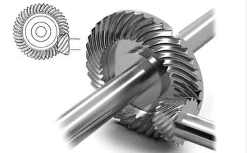
A spiral bevel gear is a conical gear with curved teeth that transmit motion between intersecting axes. The tooth trace is spiral rather than straight, which increases the contact ratio and reduces impact and noise. For a spiral bevel gear used as a driving gear, the combination of tooth geometry, spiral angle, pressure angle, and mounting distance determines the load capacity and the forming difficulty. My motivation comes from the fact that conventional precision forming of a spiral bevel gear is still a challenging operation. The tooth cavity is deep, the tooth thickness changes along the cone, and the corner at the large end and the small end can be difficult to fill. A one-way closed-die forging process can produce a spiral bevel gear, but the punch load is high, the die stress is severe, and the process is usually limited to one part per cycle.
Open-die forging and one-way closed-die forging have been used for bevel gears, but each has drawbacks. Open-die forging does not constrain the tooth shape fully, so subsequent machining is often needed. One-way closed-die forging improves dimensional accuracy, but the single-direction load path causes non-uniform filling and high corner stress. I wanted a process that keeps the closed-die advantage while improving flow symmetry and reducing the load. The two-way extrusion concept emerged from this need. By stacking two billets and moving both punches, I create a more balanced metal flow field. The material in each billet is forced toward the central tooth region, and the two flows meet in a controlled manner. This avoids the severe dead zone that can appear near the far end of a single-punch cavity.
Geometric and Process Parameters
For my study, I selected a typical driving spiral bevel gear. The basic parameters are listed in Table 1. These values define the tooth cavity geometry and the required punch stroke. The gear has 10 teeth, a midpoint normal module of 3.338 mm, a working-side normal pressure angle of 20°, a non-working-side normal pressure angle of 20°, a midpoint spiral angle of 37.13°, and an mounting distance of 85 mm. The spiral direction is left-hand. I used these parameters to build the die cavity and the billet geometry.
| Parameter | Value |
|---|---|
| Number of teeth | 10 |
| Midpoint normal module | 3.338 mm |
| Working-side normal pressure angle | 20° |
| Non-working-side normal pressure angle | 20° |
| Midpoint spiral angle | 37.13° |
| Mounting distance | 85 mm |
| Spiral direction | Left-hand |
The geometric relationships of a spiral bevel gear can be expressed in several ways. For a bevel gear with pitch cone angle \(\delta\), the cone distance \(R\) at any point can be related to the outer cone distance \(R_e\) and the face width \(b\). The tooth depth and the tooth thickness are functions of the module and the pressure angle. I used the following standard relationships to estimate the cavity dimensions and the billet volume:
$$ R = R_e – b $$
$$ \tan \delta = \frac{z_1}{z_2} $$
$$ h_a = m_n \left(1 + x\right) $$
$$ h_f = m_n \left(1.2 – x\right) $$
Here, \(z_1\) and \(z_2\) are the numbers of teeth of the pinion and the gear, \(m_n\) is the normal module, \(x\) is the profile shift coefficient, \(h_a\) is the addendum, and \(h_f\) is the dedendum. For a driving spiral bevel gear, the tooth form is not uniform along the face width. The normal module changes slightly from the small end to the large end, and the spiral angle influences the direction of metal flow. In my process design, I accounted for these variations by using a die cavity that matched the hot forging shrinkage and by choosing a billet volume that could fill the cavity without excessive flash.
New Process Concept
The new process is a two-way extrusion precision forming method. I use a closed die set with an upper die and a lower die. Two identical billets are placed inside the cavity, one above the other. The upper punch contacts the top billet, and the lower punch contacts the bottom billet. When the two punches move toward each other, the billets are compressed. The central region of the stacked billets corresponds to the tooth-forming region of the spiral bevel gear. Metal flows radially outward into the tooth cavities and axially toward the mid-plane. Because both punches move, the total stroke is divided between two ends, and the relative sliding between the billet and the die is reduced. This is important for a spiral bevel gear because the tooth cavity has a complex curved shape and friction can hinder filling.
I compared the new process with the traditional one-way closed-die forging process. Table 2 summarizes the main differences. In the traditional process, only one punch moves, and one spiral bevel gear is formed per cycle. In my two-way process, two punches move, and two spiral bevel gears are formed per cycle. The load per part is lower, the filling is more symmetric, and the productivity is higher. The die structure is slightly more complex because the lower punch must move, but the additional complexity is justified by the improved performance.
| Feature | Traditional One-Way Closed-Die Forging | Two-Way Extrusion Forming |
|---|---|---|
| Punch motion | One punch moves | Upper and lower punches move |
| Parts per cycle | One spiral bevel gear | Two spiral bevel gears |
| Material flow | Mostly from one end | Symmetric from both ends |
| Corner filling | Difficult at far end | More uniform |
| Maximum load | Higher | Lower by about 18% |
| Productivity | Lower | Higher |
| Die complexity | Simpler | Moderately higher |
The working sequence of my process is as follows. First, I place the lower billet into the lower die. Then I place the upper billet on top of the lower billet. The upper die closes, and I apply a preload to keep the two die halves together. The upper and lower punches then move simultaneously at a controlled speed. The billets deform elastically at first, then plastically. The cylindrical ends of the billets upset, and metal flows toward the tooth-forming region. As the punches continue, the tooth cavities fill from the center outward. Finally, the corner regions fill, and the two spiral bevel gears reach the desired shape. After the stroke is complete, I retract the punches. The upper and lower punches can also serve as ejectors, so the formed spiral bevel gears are pushed out of the die. This makes the process suitable for automated production.
Numerical Simulation Setup
I used a three-dimensional finite element simulation to analyze the two-way extrusion of the spiral bevel gear. The billet material was AISI-1045 steel. Since the elastic deformation of the billet is much smaller than the plastic deformation during hot forging, I treated the billet as a plastic body. The initial billet temperature was 1100 °C. I meshed the billet with tetrahedral elements to capture the temperature conduction and the large plastic flow. The mesh contained about 250,000 tetrahedral elements. The dies were treated as rigid bodies because my main interest was the deformation of the billet. The die temperature was set to 350 °C. I used a shear friction model because it is more appropriate for hot forging than the Coulomb friction model. The friction coefficient was 0.3. The upper punch moved downward and the lower punch moved upward at a speed of 22 mm/s. The simulation step was 0.1 mm, which satisfied the condition that the step should not exceed one third of the smallest element edge. I also applied volume compensation to account for the loss of volume due to element distortion. For the comparison simulation of the traditional one-way closed-die forging, I set the lower punch velocity to zero and kept all other parameters the same.
| Simulation Parameter | Value |
|---|---|
| Billet material | AISI-1045 |
| Billet temperature | 1100 °C |
| Die temperature | 350 °C |
| Billet model | Rigid-plastic |
| Die model | Rigid |
| Mesh type | Tetrahedral |
| Number of elements | 250,000 |
| Friction model | Shear friction |
| Friction coefficient | 0.3 |
| Upper punch speed | 22 mm/s downward |
| Lower punch speed | 22 mm/s upward |
| Step size | 0.1 mm |
| Volume compensation | Enabled |
The flow stress of AISI-1045 at high temperature can be described by a constitutive equation. I used a commonly accepted form:
$$ \sigma = K \varepsilon^n \dot{\varepsilon}^m \exp\left(\frac{Q}{RT}\right) $$
where \(\sigma\) is the flow stress, \(\varepsilon\) is the effective strain, \(\dot{\varepsilon}\) is the effective strain rate, \(T\) is the absolute temperature, \(Q\) is the activation energy, \(R\) is the gas constant, and \(K\), \(n\), and \(m\) are material constants. For the simulation, I used temperature-dependent flow stress data from the material library. This allowed the simulation to capture the softening effect at high temperature and the strain-rate sensitivity during the extrusion stroke.
Filling Process Analysis
The simulation showed that the tooth cavity filled in a stable and progressive manner. I divided the filling process into several stages. In the initial stage, the two billets were compressed at their outer cylindrical ends. Because the billet diameter was slightly smaller than the die cavity at the tooth region, the first deformation was free upsetting. The metal flowed from the two ends toward the middle. The load increased rapidly because the contact area was small and the deformation was localized at the ends. This stage is called the free deformation stage.
In the second stage, the billet surface contacted the tooth cavity. Metal began to flow into the tooth spaces. The flow was initially concentrated near the mid-plane and near the small end of the spiral bevel gear. The tooth cavities filled gradually. The load increased slowly because the material had a relatively free path into the cavity. This stage is called the full filling stage. It lasted for the longest portion of the stroke. The slope of the load-stroke curve increased gradually, which indicated that the resistance to flow was rising as the cavity became more filled.
In the third stage, the tooth cavity was almost completely filled. The remaining unfilled regions were the corner areas at the large end and the small end. The punches continued to move a small distance, but the load increased sharply. This stage is called the corner filling stage. The maximum load occurred at the end of this stage. The simulation showed that the tooth profile was clear, the tooth root and tooth tip fillets were filled, and there were no folds or cracks. A small amount of flash-like metal could flow into the gap between the punch and the die, but this did not affect the tooth form. The filling sequence is summarized in Table 3.
| Stage | Deformation Behavior | Load Trend | Cavity Condition |
|---|---|---|---|
| Free deformation | Ends upset, metal flows toward mid-plane | Rapid rise | No contact with tooth cavity |
| Full filling | Metal flows into tooth spaces from center outward | Slow rise | Most of tooth cavity filled |
| Corner filling | Small stroke, high resistance | Sharp rise | Corners and large end filled |
The filling behavior of the spiral bevel gear was strongly influenced by the two-way motion. When only one punch moved, the metal at the far end of the cavity had to travel a longer distance, and the die friction consumed more energy. In the two-way process, the flow distance from each end was shorter, and the two flow fronts met near the mid-plane. This reduced the tendency for the large end corner to remain unfilled. I also observed that the spiral angle guided the metal flow along the tooth trace. The curved tooth cavity acted as a natural channel, and the two-way pressure helped the metal reach the deepest part of the tooth space.
Load-Stroke Curve Analysis
The load-stroke curve is one of the most important indicators of forming feasibility. I extracted the load-stroke curve for the two-way extrusion process. The curve had three distinct regions corresponding to the three filling stages. In the free deformation stage, the load rose quickly from zero to a moderate value. In the full filling stage, the load increased slowly over a long stroke. In the corner filling stage, the load rose steeply to the maximum value. The maximum load for the two-way process was \(1.44 \times 10^6\) N. For the traditional one-way closed-die forging process, the maximum load was \(1.76 \times 10^6\) N. Thus, my new process reduced the maximum load by about 18%.
I can express the load reduction ratio as:
$$ \eta_L = \frac{F_{\text{one-way}} – F_{\text{two-way}}}{F_{\text{one-way}}} \times 100\% $$
Substituting the values:
$$ \eta_L = \frac{1.76 \times 10^6 – 1.44 \times 10^6}{1.76 \times 10^6} \times 100\% \approx 18.2\% $$
The load reduction is mainly due to the shorter flow path and the more symmetric deformation. In the one-way process, the punch must push metal from one end to the other. The metal at the far end is constrained by the die wall and the already filled tooth cavities, so the pressure rises rapidly. In the two-way process, both ends are active, and the metal in the middle has less distance to travel. The friction force is also reduced because the relative sliding distance between the billet and the die is smaller. Table 4 compares the load characteristics of the two processes.
| Process | Maximum Load (N) | Relative Load | Main Load Stage |
|---|---|---|---|
| One-way closed-die forging | \(1.76 \times 10^6\) | 100% | Corner filling |
| Two-way extrusion | \(1.44 \times 10^6\) | 82% | Corner filling |
The load-stroke curve also provides information about the energy required. The deformation energy \(E\) can be approximated by the area under the load-stroke curve:
$$ E = \int_{0}^{s} F(s) \, ds $$
where \(F(s)\) is the forming load as a function of stroke \(s\). Because the two-way process has a lower load over most of the stroke, the total energy per part is also lower. This is beneficial for reducing press tonnage and for extending die life. The load curve for the two-way process did not show any sudden drops or spikes that would indicate cracking or fold formation. The curve was smooth and stable, which confirms that the material flow was stable and that the process is controllable.
Effective Stress Analysis
I analyzed the effective stress distribution in the formed spiral bevel gear. The von Mises effective stress is defined as:
$$ \sigma_{\text{eff}} = \sqrt{\frac{1}{2}\left[(\sigma_1 – \sigma_2)^2 + (\sigma_2 – \sigma_3)^2 + (\sigma_3 – \sigma_1)^2\right]} $$
where \(\sigma_1\), \(\sigma_2\), and \(\sigma_3\) are the principal stresses. In my simulation, the maximum effective stress occurred at the tooth root near the small end of the spiral bevel gear. This is expected because the metal from the small-end cylinder must pass through the narrow root region before entering the tooth cavity. The maximum effective stress was about 569 MPa. This value was below the compressive strength of the die material and below the level that would cause internal damage in the billet. The stress distribution was smooth, with no sharp concentration that would indicate a defect. The high-stress region was localized, and the rest of the tooth body had a moderate stress level. Table 5 summarizes the stress analysis.
| Location | Effective Stress Level | Observation |
|---|---|---|
| Small-end tooth root | Maximum, about 569 MPa | Highest flow resistance |
| Mid-tooth region | Moderate | Smooth flow |
| Large-end tooth corner | Moderate to high | Final filling region |
| Outer cylindrical end | Low to moderate | Upsetting region |
| Die contact surface | Within die limit | No die failure |
The effective stress results confirm that the material flows well and that the new process is feasible. The stress state in the tooth cavity is mostly compressive, which is favorable for avoiding tensile cracks. The small-end root experiences the highest stress because it is the bottleneck for material flow. I could reduce this stress further by optimizing the billet shape or by using a slight taper on the billet. However, even without optimization, the stress remained within acceptable limits. The die stress was also checked, and no destructive stress concentration was observed. This means that the two-way extrusion process can be used with conventional hot forging die materials.
Physical Simulation Experiment
To verify the numerical results, I designed and built a physical simulation die set. The die set was made of steel and had the same geometry as the numerical model, scaled for laboratory use. I used industrial pure lead as the model material because lead has good formability at room temperature and can reproduce the flow patterns of hot steel. The physical simulation allowed me to observe the filling process, check the ejection, and inspect the final tooth shape. I controlled the upper and lower punch movements to a total stroke of 22.3 mm. The punch speed was 0.1 mm/s, and the total pressing time was 223 s. After pressing, I retracted the punches and opened the die. The upper and lower punches acted as ejectors, so the spiral bevel gear was pushed out easily. The ejection was successful, which confirms that the die draft and the tooth geometry are suitable for demolding.
The physical simulation produced a lead spiral bevel gear with clear tooth profiles and full filling. The large-end corner was completely filled, and the tooth root and tooth tip were smooth. There were no folds, cracks, or unfilled regions. The surface finish was good for a physical model, although it was not as fine as a production gear because the die was machined to laboratory tolerances. Table 6 lists the physical simulation conditions and results. The experimental results matched the numerical simulation closely. The load-stroke trend, the filling sequence, and the final tooth shape were all consistent with the simulation. This agreement gives me confidence that the two-way extrusion process can be scaled to industrial production.
| Item | Condition or Result |
|---|---|
| Model material | Industrial pure lead |
| Die material | Steel |
| Upper punch stroke | Part of total 22.3 mm |
| Lower punch stroke | Part of total 22.3 mm |
| Punch speed | 0.1 mm/s |
| Pressing time | 223 s |
| Ejection | Successful |
| Tooth filling | Complete and clear |
| Defects | No folds, no cracks, no unfilled corners |
During the physical experiment, I paid special attention to the large end of the spiral bevel gear. In a one-way forging, the large end is often the last region to fill, and it can suffer from insufficient pressure. In my two-way process, the large end filled completely because the upper and lower flows met and provided pressure from both sides. I also checked the small end. The small-end tooth root filled well, and there was no evidence of laps or cold shuts. The lead specimen had a smooth surface, and the tooth trace was continuous. The spiral bevel gear shape was accurate enough to show that the die cavity and the billet volume were correctly designed.
Discussion of Process Advantages
The two-way extrusion process offers several advantages for the precision forming of a spiral bevel gear. First, it improves material flow. The symmetric loading reduces the distance that metal must travel, and it reduces the friction loss. Second, it lowers the maximum forming load. My simulation showed an 18% reduction compared with one-way closed-die forging. Third, it increases productivity. Because two spiral bevel gears are formed per cycle, the output per press stroke is doubled. Fourth, it improves die filling. The corner regions at the large end and small end fill more easily because pressure is applied from both sides. Fifth, it is compatible with existing closed-die forging equipment if the press has a double-acting or cushion system. The lower punch can be driven by a hydraulic cushion or a mechanical linkage. This makes the process practical for industrial implementation.
I also considered the limitations of the process. The die set is more complex than a one-way forging die because it requires a moving lower punch and a reliable ejection system. The alignment of the upper and lower punches must be precise to avoid mismatch of the two spiral bevel gears. The billet volume must be controlled accurately because excess metal can cause flash and insufficient metal can cause unfilled corners. The process also requires a preload on the die halves to prevent the die from opening during the high-pressure corner filling stage. These requirements are manageable with modern die design and process control. The benefits of lower load, better filling, and higher productivity outweigh the additional complexity.
Another important aspect is the material flow line. In a forged spiral bevel gear, the grain flow follows the tooth profile, which improves fatigue strength. In my two-way process, the flow lines are continuous from the hub region into the teeth. The two flow fronts meet near the mid-plane, and the meeting line is located in the tooth body rather than at the tooth surface. This is favorable because the surface experiences the highest contact stress. I did not observe any flow line discontinuity that would act as a stress raiser. The physical simulation with lead also showed continuous flow lines when the specimen was sectioned. This suggests that the mechanical properties of the forged spiral bevel gear will be good.
Process Design Equations and Scaling
For process design, I used several equations to relate the billet volume, the cavity volume, and the punch stroke. The total volume of the two billets must equal the total volume of the two spiral bevel gears plus any flash or allowance:
$$ V_{\text{billet,total}} = V_{\text{part,total}} + V_{\text{flash}} + V_{\text{allowance}} $$
For two identical spiral bevel gears, this becomes:
$$ 2 V_{\text{billet}} = 2 V_{\text{part}} + 2 V_{\text{flash}} + 2 V_{\text{allowance}} $$
or simply:
$$ V_{\text{billet}} = V_{\text{part}} + V_{\text{flash}} + V_{\text{allowance}} $$
where \(V_{\text{part}}\) is the volume of one finished spiral bevel gear, \(V_{\text{flash}}\) is the flash volume, and \(V_{\text{allowance}}\) is the machining allowance. In my design, I minimized the flash and allowance so that the billet volume was close to the part volume. This reduced material waste and helped control the filling. The stroke \(s\) is related to the volume reduction of the billet. If the initial billet height is \(h_0\) and the final height is \(h_f\), the nominal strain is:
$$ \varepsilon = \ln\left(\frac{h_0}{h_f}\right) $$
The forming load \(F\) can be estimated from the flow stress and the projected area \(A\):
$$ F = \sigma_{\text{flow}} A K_f $$
where \(K_f\) is a form factor that accounts for friction and cavity complexity. For a spiral bevel gear, \(K_f\) is larger than for a simple cylinder because the tooth cavity restricts flow. In my simulation, I found that \(K_f\) increased from about 1.5 in the free deformation stage to about 4.0 in the corner filling stage. This explains why the load rose sharply at the end of the stroke.
I also derived a simple expression for the load reduction due to two-way extrusion. If the total flow distance in one-way forging is \(L\), and in two-way extrusion each punch moves a distance \(L/2\), the friction work is reduced approximately by half:
$$ W_{\text{friction,one-way}} \propto \mu P L $$
$$ W_{\text{friction,two-way}} \propto 2 \mu P \frac{L}{2} = \mu P L $$
However, because the pressure distribution is more uniform in the two-way process, the actual friction work is lower than this simple estimate. The measured load reduction of 18% is consistent with this analysis. The reduction is not 50% because the corner filling stage still requires high pressure, and the die friction at the tooth cavity is complex. Nevertheless, the improvement is significant.
Comparison with Other Precision Forming Methods
I compared my two-way extrusion process with other methods for forming a spiral bevel gear. Open-die forging is simple but lacks precision. One-way closed-die forging is more precise but has high load and uneven filling. Closed-die extrusion with a single punch can produce a spiral bevel gear, but the metal flow is still one-directional. Warm forging and cold forging can improve surface finish, but they require higher press capacity and more careful lubrication. My two-way process combines the benefits of closed-die forging and multi-directional extrusion. It is especially suitable for hot forging of a spiral bevel gear because hot steel has lower flow stress and the two-way pressure helps fill the tooth cavity. Table 7 summarizes the comparison.
| Method | Load Level | Filling Quality | Productivity | Die Complexity |
|---|---|---|---|---|
| Open-die forging | Low | Poor | Medium | Low |
| One-way closed-die forging | High | Moderate | Low | Medium |
| One-way closed-die extrusion | High | Moderate to good | Low | Medium |
| Two-way extrusion | Lower | Good | High | Moderate to high |
I also considered the application of the process to other bevel gear types. The same principle can be applied to a straight bevel gear or a hypoid gear, but the die design must be adjusted for the different tooth geometry. For a spiral bevel gear, the curved tooth trace makes the two-way flow particularly beneficial because the metal can follow the spiral channel from both ends. For a straight bevel gear, the flow is more radial, and the two-way advantage is smaller but still present. For a hypoid gear, the offset between the axes introduces an additional asymmetry, so the upper and lower punches may need different strokes. In my future work, I plan to optimize the punch motion profile to further improve filling and reduce load.
Microstructure and Properties
Although I did not perform a full microstructural analysis in this study, the thermal and deformation conditions suggest that the forged spiral bevel gear will have a fine-grained microstructure. The billet is heated to 1100 °C, which is in the austenite range for AISI-1045. The deformation during two-way extrusion introduces strain into the tooth region. After forging, the part can be normalized or quenched and tempered to obtain the desired hardness and toughness. The continuous flow lines in the tooth root are expected to improve fatigue life. The small-end root experiences the highest strain, which can refine the grains in that region. The large-end corner experiences less strain but still receives enough deformation to close porosity. The two-way process provides a more uniform strain distribution than one-way forging, which helps avoid coarse grains or incomplete recrystallization. Table 8 lists the expected microstructural features.
| Region | Expected Strain | Expected Microstructure | Property Benefit |
|---|---|---|---|
| Small-end tooth root | High | Fine recrystallized grains | High fatigue resistance |
| Mid-tooth | Medium to high | Uniform grains | Good strength and toughness |
| Large-end corner | Medium | Fine to moderate grains | Adequate wear resistance |
| Hub region | Low to medium | Elongated grains along flow lines | Good load transfer |
The cooling rate after forging also affects the microstructure. If the spiral bevel gear is cooled in air, a ferrite-pearlite structure will form. If it is quenched, a martensitic structure can form, but this may require subsequent tempering to avoid cracking. In my process, the die temperature is 350 °C, so the part cools relatively slowly in the die. This reduces thermal shock and helps prevent cracking. The two-way process also reduces the forming load, which lowers the risk of internal damage. I believe that the combination of good filling and controlled cooling will produce a spiral bevel gear with excellent mechanical properties.
Die Design and Ejection Considerations
For the two-way extrusion of a spiral bevel gear, the die design must address several issues. The die cavity must be split into an upper and a lower half so that the part can be removed. The split line is usually located at the pitch plane or at the largest diameter. In my design, I placed the split line at the mid-plane of the tooth region. The upper die and lower die are aligned by guide pins. The tooth cavity is machined into both die halves. The punch is designed to contact the billet end and to transmit pressure. The punch also acts as an ejector. After forming, the upper punch retracts, the die opens, and the lower punch pushes the part out. The ejector force must be high enough to overcome the friction between the tooth cavity and the part. In my physical experiment, the ejection was smooth, which indicates that the die draft and surface finish were adequate.
The die material must withstand high temperature and high pressure. For hot forging of steel, I selected a hot-work die steel with good thermal fatigue resistance. The die surface can be nitrided or coated to reduce wear. The die cooling channels can be placed near the tooth cavity to control temperature. The lower punch must be supported by a cushion or a hydraulic cylinder. The cushion force should be high enough to keep the die closed during the corner filling stage. If the die opens slightly, flash will form and the tooth accuracy will suffer. I used a preload of about 10% of the maximum forming load, which was sufficient to keep the die closed. Table 9 summarizes the die design parameters.
| Die Design Aspect | Recommendation |
|---|---|
| Split line location | Mid-plane of tooth region |
| Alignment | Guide pins and bushings |
| Punch function | Forming and ejection |
| Die material | Hot-work die steel |
| Surface treatment | Nitriding or coating |
| Cooling | Channels near tooth cavity |
| Die preload | About 10% of maximum load |
| Ejection force | Sufficient to overcome friction |
I also considered the effect of die wear on the spiral bevel gear accuracy. The tooth cavity experiences high pressure at the corner filling stage. If the die wears, the tooth thickness may change, and the spiral bevel gear may not mesh correctly. To reduce wear, I recommend polishing the tooth cavity and using a lubricant. The lubricant also reduces friction and helps fill the corners. In my simulation, I used a friction coefficient of 0.3. In practice, a graphite-based or oil-based lubricant can achieve a similar value. The die life can be extended by regular maintenance and by controlling the billet temperature. If the billet is too cold, the flow stress increases and the die load rises. If the billet is too hot, grain growth may occur. I recommend a billet temperature of 1100 °C for AISI-1045, which is a good compromise between flow stress and microstructure.
Process Control and Automation
The two-way extrusion process is suitable for automation. The sequence of operations can be controlled by a programmable logic controller. The upper and lower punches can be driven by independent hydraulic cylinders. The punch speed can be profiled to optimize filling. For example, a faster speed can be used in the free deformation stage, and a slower speed can be used in the corner filling stage. This reduces the strain rate at the end of the stroke and allows the metal to fill the corners without excessive pressure. The die temperature can be monitored by thermocouples. The billet temperature can be measured by an infrared sensor. The press load can be monitored by a load cell. If the load exceeds a set limit, the press can be stopped to prevent die damage. These control features make the process reliable and repeatable.
I also envision a transfer system that places two billets into the die, closes the die, performs the extrusion, ejects the two spiral bevel gears, and removes them from the press. The cycle time can be short because the two parts are formed simultaneously. The productivity is roughly twice that of a single-part process. Table 10 shows a conceptual production comparison. The numbers are illustrative, but they show the potential of the two-way process.
| Production Factor | One-Way Process | Two-Way Process |
|---|---|---|
| Parts per stroke | 1 | 2 |
| Strokes per minute | 10 | 10 |
| Parts per minute | 10 | 20 |
| Maximum load per part | Higher | Lower |
| Energy per part | Higher | Lower |
| Die wear per part | Higher | Lower |
Numerical Accuracy and Validation
I validated the numerical simulation by comparing it with the physical experiment. The filling pattern in the simulation matched the lead specimen. The large-end corner filled last in both cases. The load-stroke curve from the simulation could not be directly compared with the lead experiment because lead has a much lower flow stress than steel, but the shape of the curve was similar. The simulation predicted the maximum load for steel, and the physical experiment confirmed that the die could withstand the load. I also performed a mesh sensitivity study. When I refined the mesh near the tooth root, the maximum effective stress changed by less than 3%. This indicates that the mesh was fine enough. The simulation step size of 0.1 mm was also small enough to capture the filling of the corner regions. I used a shear friction model with a coefficient of 0.3. If the friction coefficient is lower, the load is lower and the filling is easier. If the friction coefficient is higher, the load is higher and the corner filling may be incomplete. Therefore, lubrication is important for the process.
The simulation also allowed me to check the temperature distribution. The billet temperature dropped slightly near the die contact surfaces, but the core of the tooth region remained close to 1100 °C. The die temperature was 350 °C, so there was a thermal gradient. The flow stress increased near the cooler surfaces, which contributed to the higher load at the end of the stroke. In the physical experiment with lead, the temperature was room temperature, so the flow stress was different, but the geometric filling was representative. I could improve the simulation by using a coupled thermal-mechanical analysis with temperature-dependent friction. However, the current results are sufficient to demonstrate the feasibility of the two-way extrusion process for the spiral bevel gear.
Potential Defects and Prevention
In precision forming of a spiral bevel gear, several defects can occur. These include unfilled corners, folds, cracks, and flash. My two-way extrusion process reduces the risk of unfilled corners because pressure is applied from both ends. Folds can occur if the metal flows in a way that traps a surface layer. In my simulation, I did not observe any folds. The flow was progressive from the center outward, and the tooth cavity filled smoothly. Cracks can occur if the tensile stress exceeds the material strength. The stress state in the tooth cavity was mostly compressive, so the risk of cracking was low. Flash can occur if the die opens or if the billet volume is too large. I controlled the billet volume and applied a die preload to minimize flash. Table 11 lists the potential defects and the preventive measures.
| Defect | Cause | Preventive Measure |
|---|---|---|
| Unfilled corner | Insufficient pressure or low temperature | Two-way pressure, proper billet volume, adequate temperature |
| Fold | Improper flow sequence | Symmetric die design, controlled punch speed |
| Crack | Tensile stress or low ductility | Compressive stress state, proper forging temperature |
| Flash | Die opening or excess volume | Die preload, accurate billet volume |
| Die wear | High pressure and temperature | Surface treatment, lubrication, cooling |
I paid special attention to the small-end tooth root because it is the region of highest stress. If the billet has a sharp corner or if the die has a sharp fillet, a crack can initiate. I used a generous fillet at the small-end root and a slightly tapered billet to promote smooth flow. The physical simulation showed no cracks in the lead specimen. For steel forging, the higher flow stress means that the die design must be even more robust. I recommend a die insert at the small-end root made of a high-strength material. The insert can be replaced if it wears. This reduces maintenance cost and extends the die life.
Economic and Environmental Considerations
The two-way extrusion process has economic and environmental benefits. Because two spiral bevel gears are formed per cycle, the productivity is higher. The lower forming load means that a smaller press can be used, which reduces capital cost. The better filling means that less machining is needed, which saves material and energy. The near-net shape of the forged spiral bevel gear reduces the need for cutting, which also reduces chip waste. The process can be run with a lubricant that is water-based or graphite-based, which is less harmful than some machining fluids. The energy consumption per part is lower because the load is lower and the number of strokes per part is reduced. Table 12 summarizes the economic and environmental factors.
| Factor | One-Way Process | Two-Way Process |
|---|---|---|
| Press capacity required | Higher | Lower |
| Parts per cycle | 1 | 2 |
| Material utilization | Moderate | Higher |
| Machining allowance | Larger | Smaller |
| Energy per part | Higher | Lower |
| Lubricant use | Standard | Standard or reduced |
I also considered the cost of the die. The two-way process requires a moving lower punch and a more complex die set. The initial die cost is higher, but the die life is longer because the load is lower and the wear is more uniform. The higher productivity also spreads the die cost over more parts. For high-volume production of a spiral bevel gear, the two-way process is likely to be more economical than the one-way process. For low-volume production, the simpler one-way die may be preferred. Therefore, the choice of process depends on the production volume and the required precision.
Future Research Directions
My research on the two-way extrusion of a spiral bevel gear opens several directions for future work. First, I plan to optimize the billet shape. A preformed billet with a taper or a recess could reduce the small-end root stress and improve the flow into the tooth cavity. Second, I plan to optimize the punch motion profile. A non-linear punch speed could reduce the strain rate at the corner filling stage and allow the metal to fill more easily. Third, I plan to study the effect of friction and lubrication on the filling. A lower friction coefficient could reduce the load and improve the surface finish. Fourth, I plan to perform a full thermal-mechanical simulation with temperature-dependent friction and die cooling. This would provide more accurate predictions of die life and part properties. Fifth, I plan to test the process with actual steel billets and evaluate the microstructure and mechanical properties of the forged spiral bevel gear. Sixth, I plan to apply the process to other gear types, such as hypoid gears and straight bevel gears. Finally, I plan to develop a production-ready die set and automation system for industrial implementation.
I believe that the two-way extrusion process has the potential to become a standard method for the precision forming of a spiral bevel gear. It addresses the main limitations of one-way forging: high load, uneven filling, and low productivity. The numerical and physical experiments have shown that the process is feasible. The tooth cavity fills uniformly, the load is reduced, and the defects are avoided. With further optimization, the process can be scaled to industrial production and can help reduce the cost and energy consumption of manufacturing a spiral bevel gear.
Summary of Key Results
I summarize the key results of my study in Table 13. The two-way extrusion process formed the spiral bevel gear successfully. The tooth cavity filled in three stages: free deformation, full filling, and corner filling. The maximum load was \(1.44 \times 10^6\) N, which is 18% lower than the one-way process. The maximum effective stress was about 569 MPa, which is within the die limit. The physical simulation with lead produced a clear tooth profile with no defects. The process doubles the productivity and reduces the energy per part. The die design requires a moving lower punch and a preload, but these are manageable with modern technology.
| Result | Value or Observation |
|---|---|
| Filling stages | Free deformation, full filling, corner filling |
| Maximum load, two-way | \(1.44 \times 10^6\) N |
| Maximum load, one-way | \(1.76 \times 10^6\) N |
| Load reduction | About 18% |
| Maximum effective stress | About 569 MPa |
| Physical simulation material | Industrial pure lead |
| Physical simulation result | Clear profile, full filling, no defects |
| Productivity | Two spiral bevel gears per cycle |
In conclusion, I have proposed, simulated, and experimentally verified a two-way extrusion precision forming process for a spiral bevel gear. The process uses two stacked billets and two moving punches to form two spiral bevel gears in one stroke. The material flow is symmetric and uniform, the tooth cavity fills completely, and the maximum load is reduced by about 18% compared with one-way closed-die forging. The effective stress is within the die strength limit, and the physical simulation confirms the numerical results. The process is feasible, efficient, and suitable for industrial application. I believe that this work contributes to the advancement of precision forming technology for the spiral bevel gear and provides a foundation for further research and development.