
Introduction
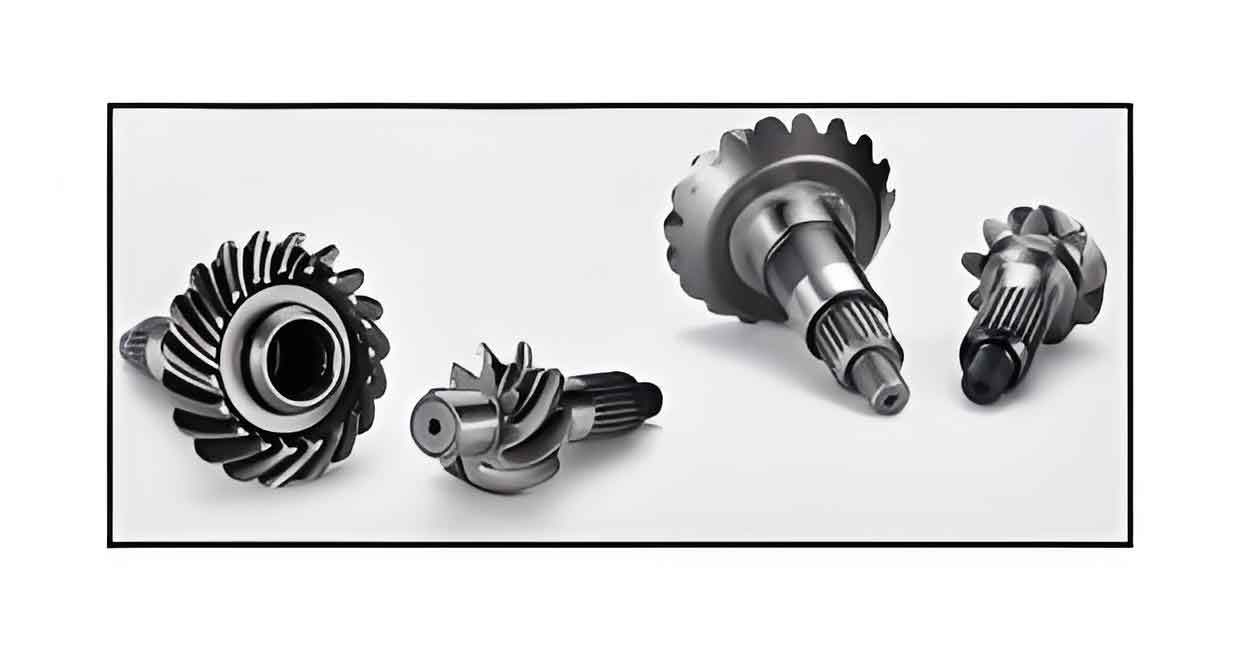
The Gear Shaft is a critical component in many mechanical systems, including automotive, aerospace, and industrial machinery. It plays a vital role in transmitting power and motion between different parts of a machine. Designing a Gear Shaft for maximum load capacity is crucial for ensuring the reliability and efficiency of these systems. This article explores the key factors involved in optimizing Gear Shaft design, including material selection, geometric dimensions, heat treatment processes, and surface finishing techniques.
Key Factors in Gear Shaft Design
- Material Selection
- Geometric Dimensions
- Heat Treatment Processes
- Surface Finishing Techniques
- Load Distribution and Stress Analysis
Material Selection
The material used for a Gear Shaft must have the necessary mechanical properties to handle high loads and resist wear and fatigue. The choice of material directly impacts the strength, toughness, and overall performance of the Gear Shaft.
Common Materials for Gear Shaft:
- Alloy Steels: Known for their high strength and toughness.
- Carbon Steels: Offer good strength and cost-effectiveness.
- Stainless Steels: Provide excellent corrosion resistance along with good mechanical properties.
- Nickel Alloys: Used for high-performance applications requiring superior toughness and fatigue resistance.
Table: Material Properties Comparison
| Material | Tensile Strength (MPa) | Hardness (HB) | Fatigue Limit (MPa) | Corrosion Resistance |
|---|---|---|---|---|
| Alloy Steel | 850-1100 | 250-300 | 400-600 | Moderate |
| Carbon Steel | 600-900 | 150-250 | 300-450 | Low |
| Stainless Steel | 600-1000 | 200-250 | 350-500 | High |
| Nickel Alloy | 900-1400 | 300-350 | 500-700 | Moderate |
Geometric Dimensions
The geometric dimensions of a Gear Shaft, including its diameter, length, and keyway size, must be optimized to balance load capacity and weight. Proper dimensioning ensures the Gear Shaft can handle the applied loads without excessive deformation or failure.
Factors to Consider:
- Diameter: Larger diameters increase load capacity but also add weight.
- Length: Must be optimized to avoid excessive deflection and ensure stability.
- Keyway Size: Proper keyway dimensions are crucial for load transmission without compromising the Gear Shaft’s strength.
Table: Geometric Dimension Considerations
| Parameter | Impact on Load Capacity | Impact on Weight |
|---|---|---|
| Diameter | Increased diameter = Higher load capacity | Increased diameter = Higher weight |
| Length | Optimized length = Reduced deflection | Excessive length = Increased weight |
| Keyway Size | Proper size = Efficient load transmission | Oversized keyway = Weakens shaft |
Heat Treatment Processes
Heat treatment processes such as quenching, tempering, and case hardening enhance the mechanical properties of Gear Shaft, improving their strength, toughness, and wear resistance.
Common Heat Treatment Techniques:
- Quenching and Tempering: Increases hardness and strength while maintaining toughness.
- Case Hardening: Provides a hard, wear-resistant surface layer while keeping the core tough.
- Nitriding: Enhances surface hardness and wear resistance through the diffusion of nitrogen.
Table: Heat Treatment Techniques
| Technique | Benefits | Applications |
|---|---|---|
| Quenching & Tempering | Increased hardness and strength, maintained toughness | General-purpose Gear Shaft |
| Case Hardening | Hard, wear-resistant surface, tough core | High-wear applications |
| Nitriding | Enhanced surface hardness and wear resistance | High-performance Gear Shaft |
Surface Finishing Techniques
Surface finishing techniques such as grinding, polishing, and coating can significantly improve the performance and lifespan of Gear Shaft by reducing friction and wear.
Common Surface Finishing Techniques:
- Grinding: Achieves precise dimensional accuracy and smooth surface finish.
- Polishing: Further smooths the surface to reduce friction.
- Coating: Applies protective layers to enhance wear and corrosion resistance.
Table: Surface Finishing Techniques
| Technique | Benefits | Applications |
|---|---|---|
| Grinding | Precise dimensional accuracy, smooth finish | All Gear Shaft |
| Polishing | Reduced friction and wear | High-speed and high-load applications |
| Coating | Enhanced wear and corrosion resistance | Harsh environmental conditions |
Load Distribution and Stress Analysis
Analyzing load distribution and stress is essential to ensure that the Gear Shaft can handle the maximum load without failure. Finite Element Analysis (FEA) is commonly used to simulate and study the stress distribution within the Gear Shaft.
Key Considerations:
- Stress Concentrations: Avoid sharp corners and sudden changes in cross-section.
- Load Distribution: Ensure uniform distribution of loads to prevent localized stresses.
- Dynamic Loads: Consider the effects of dynamic and fluctuating loads on the Gear Shaft.
List: Load Distribution Optimization Steps:
- Perform FEA: Simulate the Gear Shaft under various loading conditions.
- Identify Stress Concentrations: Locate areas with high stress and potential failure points.
- Optimize Geometry: Adjust dimensions and shapes to reduce stress concentrations.
- Validate Design: Test the optimized design under real-world conditions to ensure performance.
Conclusion
Optimizing Gear Shaft design for maximum load capacity requires a comprehensive approach that includes selecting the right materials, optimizing geometric dimensions, applying appropriate heat treatment processes, and utilizing effective surface finishing techniques. By thoroughly analyzing load distribution and stress, manufacturers can design Gear Shaft that not only meet but exceed performance requirements, ensuring reliability and longevity in various applications. Through meticulous design and testing, Gear Shaft can achieve their maximum load capacity, contributing to the overall efficiency and durability of mechanical systems.