
In the pursuit of enhancing manufacturing efficiency and component quality within the machinery sector, the focus on advanced gear production techniques is paramount. My research is dedicated to investigating the fundamental mechanics of gear hobbing, specifically under high-speed conditions. The primary objective is to develop a robust simulation methodology for analyzing the undeformed chip geometry, thickness, and the accompanying thermo-mechanical phenomena. Traditional gear hobbing processes, while effective, often grapple with issues related to tool wear, thermal damage, and suboptimal efficiency. By leveraging digital simulation tools, this study aims to provide a deep, predictive insight into the cutting process, enabling the optimization of process parameters for superior outcomes.
High-speed gear hobbing has emerged as a pivotal technology for producing transmission components in demanding applications such as aerospace and maritime industries. Characterized by cutting speeds often exceeding 150 m/min and reaching up to 400 m/min, this process offers significant advantages: increased production rates, extended tool life, and a reduced environmental footprint due to minimized or eliminated coolant usage (dry or near-dry machining). However, the practical application is frequently constrained by challenges like high tooling costs, complex chip control, and potential workpiece quality degradation due to excessive heat generation. Therefore, a scientific approach to understand and control the cutting mechanics is not just beneficial but necessary. This work introduces an integrated simulation framework to model and analyze the gear hobbing process, providing a virtual platform for process improvement before physical trials.
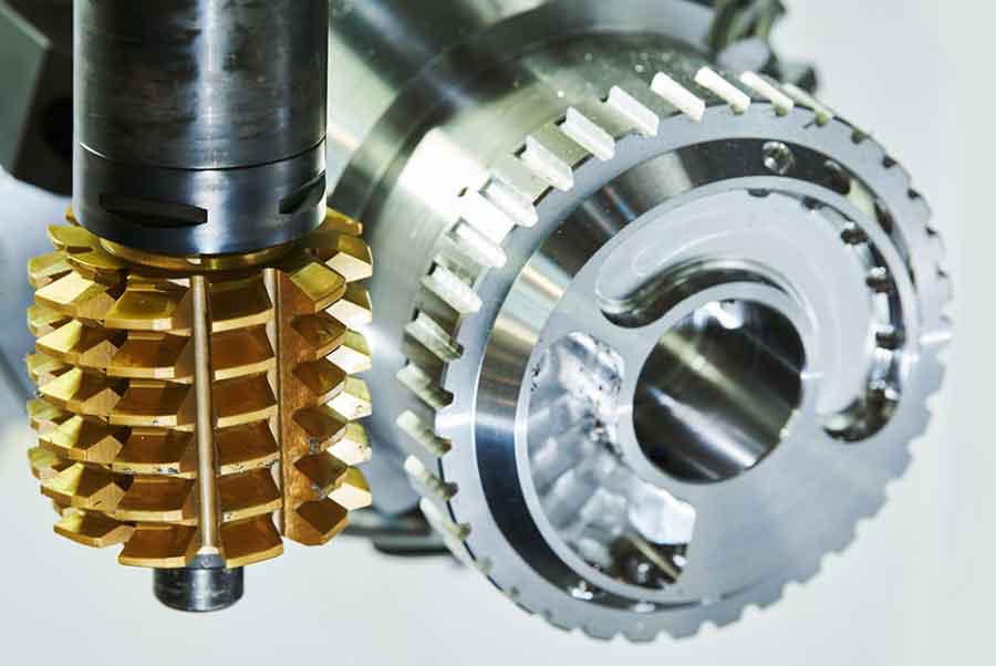
The core principle of gear hobbing is based on the continuous generating motion between the hob (a threaded cutting tool with gashes that form cutting edges) and the gear blank. This kinematic relationship, analogous to a worm gear meshing with a spur gear, allows for the progressive generation of the gear tooth profile. During the gear hobbing operation, the individual cutting edges on the hob’s helical rows engage the workpiece material sequentially, shearing away material to form the tooth spaces. The complex, synchronized motions—hob rotation, workpiece rotation, and axial feed—create a unique and dynamic cutting environment where the undeformed chip geometry changes continuously throughout the engagement. Accurately predicting this geometry is the first step toward understanding cutting forces, temperatures, and final gear quality.
Integrated Simulation Framework: From CAD to FEA
To simulate this complex interaction, I employed a multi-software workflow integrating Computer-Aided Design (CAD) and Finite Element Analysis (FEA). The process begins with the precise three-dimensional modeling of both the cutting tool and the gear blank. I utilized SolidWorks for this purpose, defining the exact geometric parameters such as hob module, number of starts, pressure angle, and gear tooth specifications. The material properties for both the tool (typically a high-speed steel or cemented carbide) and the workpiece (commonly alloy steel like AISI 4140) are also defined at this stage, including density, elastic modulus, thermal conductivity, and specific heat. These models are critical as they form the digital twins of the physical entities.
These 3D CAD assemblies are then exported in a format compatible with advanced deformation simulation software, specifically the ‘.stl’ (Stereolithography) format. The core of the analysis is performed in Deform-3D, a Lagrangian implicit code specialized for metal forming and machining processes. Upon import, the software automatically meshes the components. A key aspect of accurate simulation is mesh refinement, particularly in the anticipated shear and contact zones. For a typical simulation, the workpiece may be discretized into over 90,000 tetrahedral elements with more than 280,000 nodes, while the hob is meshed with approximately 40,000 elements. The contact interface is defined with appropriate friction models (e.g., shear friction model) and heat transfer coefficients to account for thermal interaction. The material behavior is modeled using a Johnson-Cook constitutive model, which effectively captures the strain, strain-rate, and temperature-dependent flow stress of the workpiece material:
$$ \sigma = \left(A + B \varepsilon^n \right) \left(1 + C \ln \frac{\dot{\varepsilon}}{\dot{\varepsilon}_0} \right) \left(1 – \left(\frac{T – T_{room}}{T_{melt} – T_{room}} \right)^m \right) $$
Where:
- $\sigma$ is the flow stress,
- $\varepsilon$ is the equivalent plastic strain,
- $\dot{\varepsilon}$ is the strain rate,
- $\dot{\varepsilon}_0$ is the reference strain rate,
- $T$ is the workpiece temperature,
- $T_{room}$ and $T_{melt}$ are room and melting temperatures, respectively,
- and $A$, $B$, $C$, $n$, $m$ are material constants.
The boundary conditions are set to replicate the actual gear hobbing kinematics: the hob is assigned a rotational speed and the workpiece is given a corresponding generating rotation and axial feed. The simulation then solves the coupled thermomechanical equations incrementally, tracking the deformation, stress, strain, temperature, and force evolution throughout the cut.
Simulation Results and Analysis
The simulation outputs provide a comprehensive, time-resolved view of the gear hobbing process. The analysis can be systematically broken down into several key areas.
1. Chip Formation and Morphology Evolution
The formation of the chip is a fundamental outcome of the gear hobbing process. The simulation vividly captures the evolution of the undeformed chip geometry as the hob tooth engages and exits the workpiece. Initially, at low engagement (e.g., 10% of the cutting cycle), the chip is segmented and discontinuous, primarily formed by the tool’s top and side cutting edges. As the engagement progresses to 25% and 50%, the chip transforms into a more continuous ribbon. The plastic deformation within the chip becomes severe, exhibiting the characteristic curling associated with high-speed machining. By the end of the tooth engagement (100%), a fully formed, evacuated chip is observed. This visualization allows for the direct measurement and analysis of instantaneous undeformed chip thickness ($h$), a critical parameter influencing specific cutting energy and force.
Table 1: Characteristics of Chip Formation at Different Engagement Levels
| Hob Engagement (%) | Primary Cutting Edges Active | Chip Morphology | Deformation Level |
|---|---|---|---|
| 10 | Top & Right Side | Discontinuous, segmented | Low to Moderate |
| 25 | Top, Right & Left Side | Transitioning to continuous | Moderate to High |
| 50 | Top, Right & Left Side | Continuous, ribbon-like | High (Severe curling) |
| 100 | Disengagement | Fully formed and evacuated | Complete |
2. Thermal and Velocity Field Analysis
The distribution of temperature and material velocity is crucial for understanding tool wear and workpiece integrity. The simulation reveals that during the gear hobbing operation, the highest temperatures are concentrated in the primary shear zone and at the tool-chip interface. Temperature contours typically show a range from ambient (20°C) to over 700°C in the most severe regions. The peak temperature location shifts with engagement; at mid-engagement, it resides in the central shear region, while near the end of a tooth’s cut, it localizes at the tool tip. A significant portion of the generated heat is carried away by the chip—a key benefit of high-speed gear hobbing. The velocity field analysis shows the drastic acceleration of material as it is sheared to form the chip, with streamlines clearly indicating the shear plane orientation.
Table 2: Simulated Temperature Ranges in Different Process Zones
| Process Zone | Typical Temperature Range (°C) | Remarks |
|---|---|---|
| Primary Shear Zone | 400 – 750 | Location of maximum plastic work conversion to heat. |
| Tool-Chip Interface | 300 – 650 | Critical for tool coating performance and diffusion wear. |
| Workpiece (Bulk) | 20 – 125 | Minimal temperature rise away from the cut, reducing thermal distortion risk. |
| Evacuated Chip | 500 – 700 | Acts as the primary heat sink, removing >60% of generated heat. |
3. Workpiece Stress and Strain Distribution
The mechanical load on the workpiece during gear hobbing is analyzed through equivalent (von Mises) stress and plastic strain fields. The stress distribution is highly localized. The uncut material experiences negligible stress. In the cutting zone, stress values are moderate (under 300 MPa) over most of the area, but extreme stress concentrations (exceeding 1500 MPa) are observed exactly at the contact points between the cutting edge and the workpiece material. The equivalent plastic strain shows a clear progression with cutting engagement. The peak strain value increases as more material is deformed, starting from around 0.10 at 10% engagement and rising to approximately 0.28 at 90% engagement. The high-strain region is always confined to the immediate vicinity of the cutting path, confirming the localized nature of the plastic deformation in machining.
The relationship between engagement and peak strain can be empirically observed from the simulation data. The strain accumulation is non-linear and can be approximated for this specific setup as a function of engagement angle ($\theta$):
$$ \varepsilon_{peak} \approx k_1 \cdot \theta^{k_2} $$
where $k_1$ and $k_2$ are constants derived from the simulation fit.
4. Transient Cutting Forces in Gear Hobbing
One of the most critical outputs for machine tool design and process stability is the prediction of cutting forces. The simulation tracks the three orthogonal force components (tangential/principal $F_c$, radial $F_r$, and axial $F_a$) on each hob tooth over time (or hob rotation angle). The principal cutting force $F_c$ exhibits a characteristic profile: it rises sharply at initial engagement, undergoes fluctuations as different parts of the cutting edge come into play, reaches a peak, and then decays as the tooth exits. For the simulated case, the peak force of about 670 N occurred at a hob rotation angle of roughly 13.24°. These force transients are directly linked to the changing undeformed chip thickness and the active cutting edge segments (top, left, or right). The instantaneous chip cross-sectional area $A_c$ is a primary driver of the force, related by the specific cutting pressure $K_c$:
$$ F_c(t) \approx K_c \cdot A_c(t) $$
The simulation allows for the extraction of $A_c(t)$ and the calculation of a time-varying $K_c$, offering insights into the efficiency of the cut at different stages.
Table 3: Summary of Simulated Process Outputs and Their Implications
| Simulated Output | Key Finding | Practical Implication for Gear Hobbing |
|---|---|---|
| Chip Geometry & Thickness | Varies from segmented to continuous; thickness changes dynamically. | Guides chip breaker design on the hob; helps optimize feed rates for manageable chips. |
| Temperature Field | Peak temps at shear zone & tool-chip interface; chip removes most heat. | Validates dry hobbing feasibility; informs tool material/coating selection to resist thermal softening. |
| Workpiece Stress/Strain | Extreme stress concentration at cutting edge contact; localized plastic strain. | Highlights potential for surface/subsurface damage; ensures workpiece material yield strength is not exceeded in the bulk. |
| Transient Cutting Forces | Forces fluctuate with engagement angle; peak force predictable. | Essential for machine tool rigidity assessment and spindle power calculation; aids in damping chatter vibrations. |
Validation and Application for Process Optimization
The ultimate value of a simulation model lies in its predictive accuracy and its utility for real-world process improvement. To validate the findings, the simulation parameters and outcomes were compared against a practical gear hobbing operation conducted on a YK3126 CNC hobbing machine. The workpiece was a gear with a normal module of 3 mm and 64 teeth. The process employed a two-pass strategy with different cutting depths, speeds, and feeds. The physical results showed high machining efficiency and excellent gear quality, with surface finish and dimensional accuracy meeting all specifications. The close correlation between the predicted force trends, expected chip form, and the absence of thermal damage in the actual part provided strong validation for the simulation approach.
This validated model transforms into a powerful digital twin for process optimization. Engineers can now use this framework to conduct virtual experiments, drastically reducing the need for costly and time-consuming physical trials. For instance, one can simulate the effect of varying key gear hobbing parameters:
- Cutting Speed ($V_c$): Simulating different speeds predicts changes in cutting temperature, force (often a reduction with increased speed up to a point), and chip formation mechanism (e.g., serrated chip formation at very high speeds).
- Feed Rate ($f_z$): Directly influences the undeformed chip thickness. Simulation can predict the increase in force and temperature with feed, helping to find the balance between productivity and tool load.
- Hob Geometry: The impact of different rake angles, relief angles, or edge preparations on cutting forces, stress distribution, and chip flow can be evaluated virtually.
The optimization goal can be multi-objective, aiming to minimize cutting force and temperature while maximizing material removal rate. This can be framed as finding the parameters that minimize a weighted function:
$$ \text{Objective} = w_1 \cdot \overline{F_c} + w_2 \cdot T_{max} – w_3 \cdot MRR $$
where $\overline{F_c}$ is the average principal force, $T_{max}$ is the maximum tool-chip interface temperature, $MRR$ is the Material Removal Rate, and $w_i$ are weighting factors based on priority.
Conclusion
This research demonstrates a comprehensive and effective methodology for simulating and analyzing the high-speed gear hobbing process. By integrating SolidWorks for precise geometric modeling with Deform-3D for advanced thermomechanical finite element analysis, it is possible to gain unprecedented insight into the complex interplay of events during gear generation. The simulation successfully predicts the dynamic evolution of the undeformed chip geometry and thickness, the transient state of cutting forces, the distribution of heat and stress within the workpiece, and the patterns of plastic strain. These insights are directly applicable to solving practical challenges in gear hobbing, such as optimizing process parameters for reduced tool wear, preventing workpiece thermal damage, controlling chip formation, and ensuring process stability. This digital approach empowers manufacturers to transition from empirical, trial-and-error process development to a science-based, predictive optimization strategy, ultimately leading to more efficient, reliable, and high-quality gear manufacturing.