
In modern mechanical engineering, the design of spur and pinion gears is a fundamental task, as these components are critical in power transmission systems like reducers, gearboxes, and various传动 devices. Traditional design methods often involve repetitive calculations and manual modeling, which can be time-consuming and error-prone. To address this, I have explored the application of parametric modeling techniques to enhance the flexibility and efficiency of gear design. This article details my experience in developing a parameterized design system for spur and pinion gears on the Pro/E platform, coupled with an interactive interface using Pro/TOOLKIT and VC++. By leveraging these tools, I aim to streamline the design process, allowing for quick model重建 through parameter changes, thus supporting product modification and serialized design. Throughout this discussion, I will emphasize the importance of spur and pinion gears in机械 systems and how parametric approaches can revolutionize their development.
Parametric design is a methodology where a set of parameters defines the dimensions and relationships of geometric shapes, enabling the generation of new product specifications by modifying these parameters. In essence, it involves creating a model template that captures the topological structure of a component, such as a spur and pinion gear set. The template remains consistent in topology while allowing dimensional variations through programmed controls. My implementation focuses on spur and pinion gears because their standardized yet variable nature makes them ideal for parametric approaches. The core idea is to establish active parameters that drive the model, with dependent parameters derived from mathematical relationships. This process, illustrated in Figure 1, involves defining parameters, creating a template, and using a program to rebuild models based on new inputs. For spur and pinion gears, this means that changes in齿数,模数, or other key parameters automatically update the entire gear geometry, reducing manual intervention and accelerating design cycles.
To understand the parametric design of spur and pinion gears, it is essential to first review their geometric parameters. A standard spur gear, whether serving as a pinion (the smaller gear) or a larger spur gear, is characterized by several fundamental parameters. These include the number of teeth (z), module (m), pressure angle (α), face width (b), addendum coefficient (h*_a), and dedendum coefficient (c*). For modified gears, an additional parameter like the profile shift coefficient (x) may be introduced. The dimensions of spur and pinion gears are calculated from these basic parameters using standardized formulas. For instance, the pitch diameter (d) is given by d = mz, the base diameter (d_b) by d_b = d cos α, the addendum diameter (d_a) by d_a = m(z + 2h*_a), and the dedendum diameter (d_f) by d_f = m[z – 2(h*_a + c*)]. These equations form the backbone of parametric modeling, as they define the relationships between active and dependent parameters. In my work, I have compiled these formulas into a comprehensive table to facilitate easy reference and implementation in the design system.
| Parameter Name | Calculation Formula |
|---|---|
| Pitch Diameter (d) | $$d = m \cdot z$$ |
| Base Diameter (d_b) | $$d_b = d \cdot \cos(\alpha)$$ |
| Addendum Diameter (d_a) | $$d_a = m \cdot (z + 2h^*_a)$$ |
| Dedendum Diameter (d_f) | $$d_f = m \cdot [z – 2(h^*_a + c^*)]$$ |
| Addendum Height (h_a) | $$h_a = m \cdot h^*_a$$ |
| Dedendum Height (h_f) | $$h_f = m \cdot (h^*_a + c^*)$$ |
For a typical spur and pinion gear pair, the basic parameters might vary between the spur gear and the pinion to meet specific传动 requirements. In my design example, I considered a pair consisting of a larger spur gear and a smaller pinion, both standard and satisfying continuous engagement conditions. The initial parameters are summarized in the table below, which serves as the foundation for the parametric model template. This table highlights how spur and pinion gears differ in齿数,模数, and other dimensions, yet share common parametric relationships. By defining these parameters in Pro/E, I established a model template that can be dynamically adjusted through an interactive interface.
| Parameter Name | Spur Gear (Large) | Pinion (Small) |
|---|---|---|
| Number of Teeth (z) | 50 | 17 |
| Module (m) | 3.5 | 5 |
| Pressure Angle (α) in degrees | 20 | 20 |
| Addendum Coefficient (h*_a) | 1 | 1 |
| Dedendum Coefficient (c*) | 0.25 | 0.25 |
| Profile Shift Coefficient (x) | 0 | 0 |
| Addendum Diameter (d_a) in mm | 182 | 100 |
| Dedendum Diameter (d_f) in mm | 166.25 | 77.5 |
| Base Diameter (d_b) in mm | 164.45 | 84.57 |
| Pitch Diameter (d) in mm | 175 | 90 |
| Addendum Height (h_a) in mm | 3.5 | 5 |
| Dedendum Height (h_f) in mm | 4.375 | 6.25 |
| Face Width (b) in mm | 55 | 67 |
Creating the parametric model for spur and pinion gears in Pro/E involved several steps. First, I developed a model template using feature-based modeling techniques. This template captures the geometric topology of both the spur gear and the pinion, ensuring that all elements are properly constrained and related. For instance, the tooth profile is generated based on the involute curve derived from the base circle, which depends on the pitch diameter and pressure angle. In Pro/E, I utilized the Parameters tool to define control parameters such as齿数,模数, and压力角, assigning initial values as per the table above. To enable parametric驱动, I established relationships between active parameters and dependent dimensions through the Relations tool. For the spur gear, active parameters included the number of teeth, module, and pressure angle, while for the pinion, additional parameters like face width, keyway dimensions, and chamfers were included to account for more complex design requirements. These relationships are expressed using Pro/E’s internal syntax, which translates to mathematical formulas like $$d = m \cdot z$$ and $$d_b = d \cdot \cos(\alpha)$$. By doing so, any change in an active parameter automatically triggers a rebuild of the model, updating all dependent features. This parametric approach not only saves time but also reduces errors associated with manual recalculations, making it ideal for designing custom spur and pinion gears for specific applications.
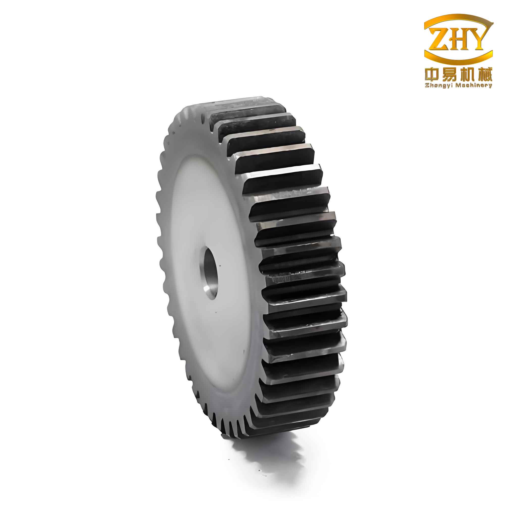
The development of an interactive interface for spur and pinion gear design was a crucial aspect of this project, as it bridges the gap between parametric modeling and user-friendly operation. I chose to use Pro/TOOLKIT, a toolkit provided by Pro/E for二次开发, along with VC++ as the programming language. The interface aims to allow designers to input parameters through a dialog box and instantly regenerate the gear models without delving into Pro/E’s native environment. I opted for the dynamic linking mode (DLL MODE) in Pro/TOOLKIT’s synchronous operation because it offers efficient function calls and data exchange, running Pro/E and Pro/TOOLKIT in the same process. This mode compiles the user-written C++ code into a DLL file, which Pro/E loads during runtime, enabling seamless communication between the interface and the model. The interface design involved creating a dialog box with various controls such as edit boxes, combo boxes, static text, and image controls. For the spur gear, I added controls for key parameters like齿数,模数, and压力角. The module, being a standardized value, was implemented using a combo box that lists standard module values from 1 to 10, with the “Sort” property disabled to maintain order. To read the selected module value into the parameter “m”, I associated an event handler in VC++ that retrieves the current selection and converts it to a numerical value. Similarly, for the pinion, more controls were added to handle additional parameters like face width, keyway width, keyway height, and chamfer size. The code snippet below illustrates how the module value is captured in the interface:
“`cpp
void CSpurPinionDialog::OnCbnSelchangeComboModule()
{
int index = m_comboModule.GetCurSel();
CString strValue;
m_comboModule.GetLBText(index, strValue);
m_module = _wtof(strValue); // Convert string to double
}
“`
This interactive interface significantly enhances the design process for spur and pinion gears. Designers can simply enter desired parameters into the dialog box, click an “OK” or “Regenerate” button, and the system will automatically update the Pro/E model based on the new inputs. For example, changing the number of teeth for the spur gear from 50 to 60, while keeping the module constant, will recalculate all related dimensions like pitch diameter and addendum diameter, and rebuild the gear model accordingly. The interface also includes validation checks to ensure that parameters are within feasible ranges, preventing errors such as undercutting in the pinion due to low tooth counts. By integrating this interface, I have made it possible to rapidly prototype various configurations of spur and pinion gears, facilitating iterative design and optimization. This is particularly useful in industries where gear specifications frequently change, such as automotive or aerospace, allowing engineers to quickly adapt to new requirements without starting from scratch.
In implementing this parametric system, I encountered several challenges and insights worth discussing. One key aspect was ensuring the accuracy of the geometric relationships for both spur and pinion gears. The involute tooth profile, which is fundamental to gear performance, must be precisely generated based on the base circle diameter. In Pro/E, I used方程 curves to define the involute, parameterized by the base diameter and pressure angle. The parametric equations for an involute curve in Cartesian coordinates are given by $$x = r_b (\cos(\theta) + \theta \sin(\theta))$$ and $$y = r_b (\sin(\theta) – \theta \cos(\theta))$$, where $$r_b$$ is the base radius and $$\theta$$ is the involute angle. By embedding these equations into the model template, I ensured that the tooth shape automatically adjusts with changes in parameters. Another challenge was handling the mating conditions between the spur gear and the pinion. For proper engagement, the center distance must satisfy $$a = \frac{m(z_1 + z_2)}{2}$$ for standard gears, where $$z_1$$ and $$z_2$$ are the tooth counts of the spur gear and pinion, respectively. In the parametric model, I included this as a derived parameter, so that modifying either gear’s齿数 updates the center distance, maintaining correct meshing. This holistic approach ensures that the entire spur and pinion gear assembly remains functionally valid across parameter variations.
The benefits of this parametric design system extend beyond mere time savings. By enabling rapid model重建, it supports系列化 design of spur and pinion gears, where a family of gears can be generated from a single template. For instance, a company might need gears with modules ranging from 2 to 10 and tooth counts from 10 to 100. With this system, designers can create a spreadsheet of parameters and batch-generate models, streamlining production and inventory management. Additionally, the interactive interface fosters collaboration between design and manufacturing teams, as non-experts can use the dialog box to input requirements without mastering Pro/E’s complex tools. In my experience, this has reduced training costs and minimized errors in gear design. Furthermore, the parametric models can be integrated with finite element analysis (FEA) tools for stress and durability testing, allowing for optimization of gear geometry based on performance criteria. For example, by varying the face width or pressure angle in the interface, engineers can quickly assess the impact on load capacity and noise levels, leading to better-designed spur and pinion gears for demanding applications.
To illustrate the practical application of this system, consider a case where a designer needs to modify an existing spur and pinion gear set for higher torque transmission. The original spur gear has 50 teeth and a module of 3.5, while the pinion has 17 teeth and a module of 5. Using the interactive interface, the designer can increase the module for both gears to 4 and 6, respectively, and adjust the tooth counts to maintain the gear ratio. The interface will instantly regenerate the models, updating all dimensions and ensuring proper meshing. The parametric relationships automatically recalculate the addendum and dedendum diameters, tooth thickness, and other critical features. This flexibility is invaluable in industries like renewable energy, where gearboxes for wind turbines require customized spur and pinion gears to handle variable loads. By leveraging parametric design, companies can reduce lead times and respond more agilely to market demands, ultimately enhancing competitiveness.
In conclusion, the parametric design and interface development for spur and pinion gears represent a significant advancement in mechanical engineering practices. By combining Pro/E’s modeling capabilities with Pro/TOOLKIT and VC++, I have created a system that simplifies and accelerates gear design. The key to success lies in defining accurate geometric parameters and their relationships, then encapsulating them in an intuitive interactive interface. This approach not only improves efficiency but also enables innovation through easy experimentation with different gear configurations. As technology evolves, such parametric systems could be extended to other gear types, like helical or bevel gears, further broadening their impact. Ultimately, the goal is to empower designers to focus on creativity and optimization, rather than repetitive tasks, thereby driving progress in the field of power transmission. The journey from concept to implementation has reinforced the value of parametric methodologies in modern engineering, and I believe that spur and pinion gears will continue to benefit from these techniques for years to come.