
In my extensive experience with gear manufacturing, I have often dealt with the challenges of gear cutting for spiral bevel gears, particularly when it comes to medium-hardness, large-scale components. Typically, in gear cutting processes for spiral bevel gears, the gear blank hardness is kept below a certain threshold to facilitate machining. However, for large-scale gears—such as those with a module greater than 10 mm and a pitch diameter exceeding 500 mm—to minimize heat treatment distortion, materials like 42CrMo or 40CrNiMo are often used in a quenched and tempered state prior to gear cutting, followed by ion nitriding. This results in gear blanks with hardness reaching 280-320 HB, which necessitates deviations from standard gear cutting adjustment methods. This article, based on the single-index single-side cutting method and focusing on the larger gear in a spiral bevel gear pair, shares my insights and practices in gear cutting for such medium-hardness, large-scale spiral bevel gears.
The gear cutting process for these gears involves unique complexities. In the single-index single-side cutting method for large gears, the roughing and finishing adjustments on the machine are identical. A cutter with a smaller tip width is used, with the first cut reaching full tooth depth, followed by rotating the gear blank to machine the other tooth flank separately to achieve the required tooth thickness. Thus, the entire gear cutting operation for the large gear consists of two cuts. However, when gear cutting medium-hardness, large-scale spiral bevel gears using this approach, several issues arise that can compromise the efficiency and quality of the gear cutting process.
During gear cutting, the process system exhibits vibration, leading to cutter chipping or breakage. Due to the high hardness of the gear blank, tool burning is prone to occur. The surface roughness of the machined tooth flanks is poor, and it tends to be inconsistent between the convex and concave sides. These problems highlight the critical need for optimized gear cutting strategies.
The root causes of these gear cutting issues are multifaceted. First, the large module of the gear means a significant volume of metal removal, and combined with the high hardness of the blank, results in substantial cutting forces during gear cutting. Second, the large diameter of the gear means the point of action of the cutting force is far from the center, leading to larger bending moments and torques on the fixture for the same cutting force. Third, the use of a large-diameter cutter head amplifies the force effects on the cutter spindle for the same cutting force. In essence, higher cutting forces, bending moments, and torques easily induce vibrations in the process system—including the machine tool, cutter, and fixture. Therefore, to address the problems in gear cutting, it is essential to reduce the cutting forces.
To mitigate these issues in gear cutting, I have implemented several practical solutions. Reducing the feed rate is a primary step. Increasing the number of cuts is another effective approach; instead of a single cut to full tooth depth, I divide it into two or even three cuts. If one tooth flank exhibits exceptionally poor roughness, in addition to the above measures, I minimize the residual stock on that flank. The specific methodology is illustrated in the application example below.
My approach to gear cutting adjustments for large gears follows the same computational principles as the standard single-index single-side cutting method, but with modifications to the cutting sequence. I will detail the gear cutting adjustments for a large gear through a concrete example, emphasizing the procedural enhancements.
| Parameter | Value | Unit |
|---|---|---|
| Module at Large End | 12 | mm |
| Number of Teeth | 41 | – |
| Mean Spiral Angle | 35° | degree |
| Pitch Diameter | 492 | mm |
| Total Tooth Depth | 21.6 | mm |
| Circular Tooth Thickness at Large End | 19.56 | mm |
| Gear Material | 42CrMo | – |
| Gear Blank Hardness | 280-320 | HB |
| Cutter Diameter | 304.8 | mm (12 inches) |
| Tip Width | 3.2 | mm |
The machine tool used is a spiral bevel gear cutting machine, and other parameters are omitted for brevity. The cutting parameters are set as follows: cutting speed of 60 m/min and machining time of 30 minutes per tooth. This gear cutting setup requires careful adjustment to avoid the aforementioned issues.
The gear cutting adjustments on the machine are performed as follows, with the entire process divided into four cuts to manage cutting forces effectively:
| Cut Number | Action | Target Depth/Thickness | Notes |
|---|---|---|---|
| 1 | Cut to initial depth | 7.2 mm | Reduces initial cutting force |
| 2 | Cut to intermediate depth | 14.4 mm | Further stock removal with controlled feed |
| 3 | Cut to full tooth depth | 21.6 mm | Final depth achieved |
| 4 | Apply additional rotation to gear blank for convex flank only | Tooth thickness of 19.56 mm | No cutting on concave flank; ensures final dimension |
In standard gear cutting, the concave flank often exhibits extremely poor roughness. Therefore, during the second and third cuts, I apply an additional rotation to the gear blank toward the convex side. This causes more material to be removed from the convex flank, while the concave flank is cut only 0.1 mm per cut. This differential stock removal helps balance the surface quality between flanks during gear cutting.
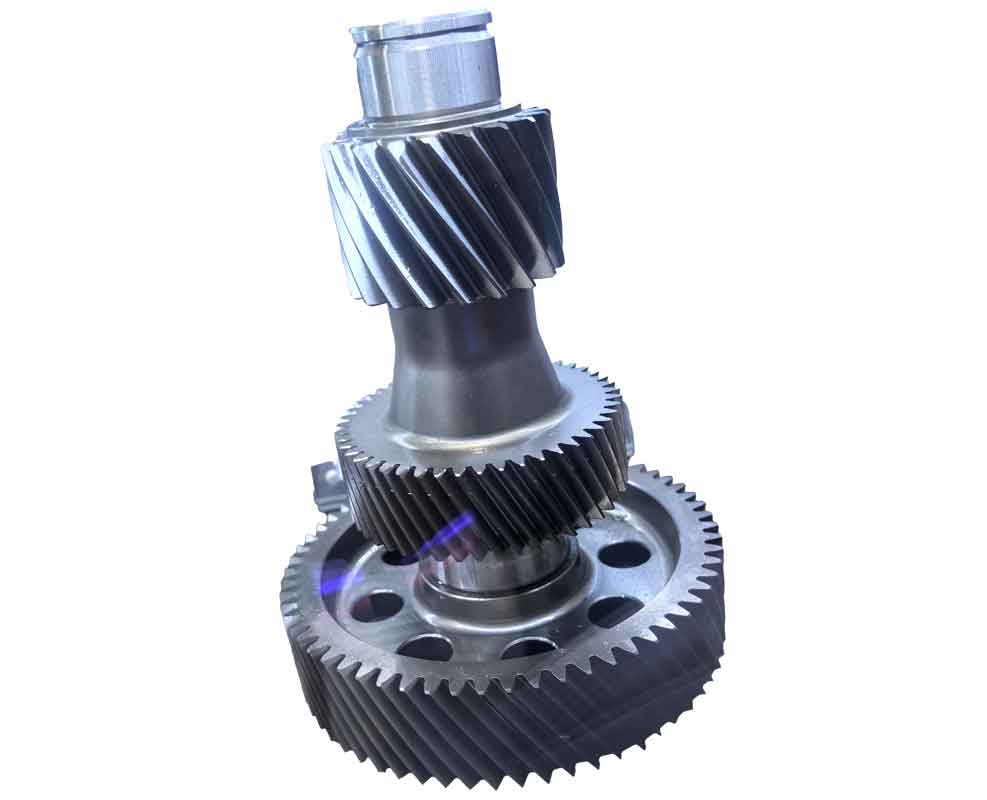
By implementing this adjusted gear cutting sequence, the machine operates without vibration, and there is no occurrence of cutter chipping or burning. The surface roughness of the gear tooth flanks achieved is approximately Ra 3.2 μm, demonstrating the effectiveness of this gear cutting approach. The following image illustrates the type of gear cutting setup and result achievable with such methods.
To further elucidate the principles behind reducing cutting forces in gear cutting, I often refer to fundamental machining formulas. The cutting force \( F_c \) in gear cutting can be approximated using the following equation, which highlights the factors influencing force generation:
$$ F_c = K_c \cdot a_p \cdot f $$
Where \( F_c \) is the cutting force (in N), \( K_c \) is the specific cutting force coefficient (in N/mm²), \( a_p \) is the depth of cut (in mm), and \( f \) is the feed rate (in mm/rev). For medium-hardness materials like 42CrMo, \( K_c \) can be relatively high. In gear cutting, reducing \( a_p \) and \( f \) directly lowers \( F_c \), which aligns with my strategy of increasing cut numbers and reducing feed. Additionally, the bending moment \( M \) on the fixture during gear cutting can be expressed as:
$$ M = F_c \cdot r $$
Where \( r \) is the distance from the cutting point to the center of rotation (in mm). For large-scale gears, \( r \) is large, so reducing \( F_c \) is crucial to minimize \( M \) and prevent vibration. This theoretical underpinning supports the practical adjustments in gear cutting.
In my gear cutting practices, I also consider the tool life and surface integrity. The Taylor tool life equation is relevant for optimizing gear cutting parameters:
$$ VT^n = C $$
Where \( V \) is the cutting speed (in m/min), \( T \) is tool life (in min), \( n \) is the Taylor exponent, and \( C \) is a constant. For hardened materials, a lower \( V \) may be chosen to extend tool life and reduce heat generation, which complements the feed reduction in gear cutting. Moreover, the surface roughness \( R_a \) in gear cutting can be influenced by feed and tool geometry, often approximated as:
$$ R_a \approx \frac{f^2}{32 \cdot r_e} $$
Where \( r_e \) is the tool nose radius (in mm). By controlling \( f \), I can improve surface finish during gear cutting. These formulas guide my decision-making in gear cutting adjustments for medium-hardness gears.
Another aspect of gear cutting is the alignment and setup accuracy. For spiral bevel gears, the machine settings involve complex geometrical calculations. The basic relationship for spiral bevel gear geometry includes the pitch diameter \( d \), module \( m \), and number of teeth \( z \):
$$ d = m \cdot z $$
In gear cutting, the cutter head settings must account for the spiral angle \( \beta \), which affects the tooth contact pattern. The mean spiral angle is critical for proper meshing. During gear cutting, I ensure that the machine is calibrated to maintain these geometrical parameters, as deviations can lead to poor gear performance. The single-index single-side method simplifies some aspects, but for medium-hardness materials, additional care is needed.
To summarize my gear cutting methodology, I have developed a comprehensive approach that integrates practical adjustments with theoretical insights. The key steps in gear cutting for medium-hardness, large-scale spiral bevel gears are as follows:
- Assessment of Gear Parameters: Before gear cutting, I analyze the gear specifications, including module, diameter, material, and hardness, to anticipate challenges.
- Selection of Cutting Strategy: I choose the single-index single-side cutting method for large gears, but adapt it by increasing the number of cuts.
- Optimization of Cutting Parameters: I reduce feed rates and depth of cut per pass to lower cutting forces, as derived from machining formulas.
- Differential Stock Removal: To address surface roughness disparities, I adjust the stock allocation between convex and concave flanks during gear cutting.
- Monitoring and Adjustment: During gear cutting, I monitor for vibrations or tool wear and make real-time adjustments to maintain quality.
This gear cutting process has proven effective in producing high-quality spiral bevel gears with improved surface finish and reduced tool wear. The integration of multiple cuts and controlled feed rates is essential for successful gear cutting of hard materials. In conclusion, gear cutting for medium-hardness, large-scale spiral bevel gears requires a tailored approach that prioritizes force reduction and process stability. By implementing the strategies outlined above, I have achieved consistent results in gear cutting, enhancing both efficiency and gear performance. The experience underscores the importance of adapting standard gear cutting methods to material-specific challenges, ensuring reliable outcomes in industrial applications.