
As a designer specializing in mechanical CAD systems, I have extensively explored parameterized drawing technology for complex components like screw gears. This technology automates the generation of production-ready drawings based on input parameters, ensuring accuracy and efficiency. In this article, I will detail the methodologies and techniques I developed for parameterized drawing of screw gears, focusing on practical implementation that meets manufacturing standards. These approaches are also applicable to other mechanical parts, providing a robust framework for CAD software development. The discussion will include workflows, supporting software, key technical challenges, and solutions, enriched with tables and formulas to summarize critical aspects.
The core of parameterized drawing for screw gears lies in its ability to adapt drawings dynamically to design changes. By inputting fundamental parameters, the system calculates all necessary dimensions and coordinates, then executes drawing instructions through specialized software packages. This process eliminates manual drafting errors and saves significant time, especially when dealing with varied screw gear configurations. Below, I outline the entire workflow, which I have refined through practical applications in designing screw gears for power transmission systems.
| Step | Description | Key Actions for Screw Gears |
|---|---|---|
| 1. Input Parameters | Enter known gear parameters such as module, teeth count, pressure angle, and lead angle. | Define variables for screw gear geometry, e.g., module $m$, number of worm threads $z_1$, gear teeth $z_2$. |
| 2. Calculate Basic Dimensions | Compute fundamental sizes like pitch diameters, center distance, and tooth profiles. | Use formulas: $d_1 = m \cdot z_1$ for worm pitch diameter, $d_2 = m \cdot z_2$ for gear pitch diameter, $a = \frac{d_1 + d_2}{2}$ for center distance. |
| 3. Calculate Coordinate Points | Determine coordinates for drawing points (e.g., tooth points, centers) and store in arrays. | Parametric equations: $x = r \cos(\theta)$, $y = r \sin(\theta)$ for circular features, with adjustments for screw gear helix. |
| 4. Call Parameterized Drawing Package | Invoke a custom drawing package that interfaces with graphics software to handle instructions. | Utilize subroutines for drawing screw gear elements, ensuring compatibility with CAD environments. |
| 5. Create Drawing Data Structure | Establish a data structure to manage drawing entities like lines, arcs, and dimensions. | Organize data for screw gear views (e.g., front, side) and sections to simplify annotation. |
| 6. Write Instruction File | Write drawing commands and data into a file that can be interpreted by graphics software. | Generate instructions for plotting screw gear drawings with layers, line types, and scales. |
| 7. Call Graphics Package | Execute the drawing by opening the instruction file in a graphics package for rendering. | Produce final screw gear drawings in formats suitable for manufacturing or documentation. |
| 8. End | Complete the process and output the drawing. | Validate the screw gear drawing for compliance with design standards. |
This structured workflow ensures that screw gear drawings are consistently generated, regardless of parameter variations. The automation reduces human error and accelerates design iterations, which is crucial for custom screw gear applications.
The parameterized drawing software for screw gears relies on supporting software packages. In my work, I used a graphics processing package that lacked native parameterization capabilities. To bridge this gap, I developed a parameterized drawing package that serves as an interface between the programming language and the graphics system. This package includes a suite of subroutines that users can call to perform drawing tasks without writing low-level graphics code. For screw gears, this means that complex operations like dimensioning, hatching, and block insertion are handled through simple function calls, abstracting the underlying complexity. The package integrates seamlessly with existing CAD tools, enabling efficient drawing of screw gears and similar components.
One of the primary challenges in parameterized drawing for screw gears is maintaining the relative stability of dimension positions. As gear dimensions change with input parameters, dimensions must be anchored to a common datum to prevent layout混乱. In screw gear drawings, I typically use the gear centerline or a key feature as the datum. For example, all horizontal dimensions are referenced from the leftmost point of the worm shaft, and vertical dimensions from the central axis. This approach ensures that when screw gear parameters like module or teeth count vary, the dimension lines shift uniformly, preserving a clean and readable drawing. The coordinate calculation follows this principle:
$$ x_i = x_{\text{datum}} + \Delta x_i, \quad y_i = y_{\text{datum}} + \Delta y_i $$
where $(x_i, y_i)$ are the coordinates for dimension $i$, $(x_{\text{datum}}, y_{\text{datum}})$ is the datum point, and $(\Delta x_i, \Delta y_i)$ are offsets derived from screw gear parameters such as pitch diameter or face width. By using this method, dimension stability is achieved across all screw gear variants.
Accurate dimension placement is another critical aspect. For linear dimensions in screw gear drawings, I employ a subroutine similar to DIMLINE, which takes parameters like start points of dimension lines, a point on the dimension line for positioning, the dimension value, and tolerances. However, in complex screw gear drawings with numerous dimensions, overlapping can occur. To mitigate this, I use a two-step process: first, draw the dimension using DIMLINE, then if the position is unsatisfactory, erase it with an ERASE command and redraw it at a specified location using a character-writing subroutine like WRITECHAR. This allows precise control over dimension text placement, ensuring clarity in screw gear drawings. The table below summarizes key subroutines for dimensioning screw gears:
| Subroutine | Purpose | Parameters Example for Screw Gears |
|---|---|---|
DIMLINE |
Draw linear dimensions | Start points $(x_1, y_1)$ and $(x_2, y_2)$ for worm length, dimension point $(x_d, y_d)$, value $L$, tolerances $\pm t$. |
WRITECHAR |
Write text at coordinates | Position $(x_w, y_w)$ for gear diameter label, text height $h$, rotation $0^\circ$, alignment centered. |
DIMANGLE |
Draw angular dimensions | Points on lines for screw gear lead angle, dimension line point, angle value $\gamma$ in degrees. |
For angular dimensions, such as the lead angle in screw gears, I use a subroutine DIMANGLE. However, to display tolerance values like $ \pm 30′ $, I erase the default angle value and rewrite it with formatted text. For instance, after calling DIMANGLE, I might erase the text and use WRITECHAR to display “$45^\circ \pm 30’$” at a specific location. This ensures that screw gear drawings meet precise annotation requirements.
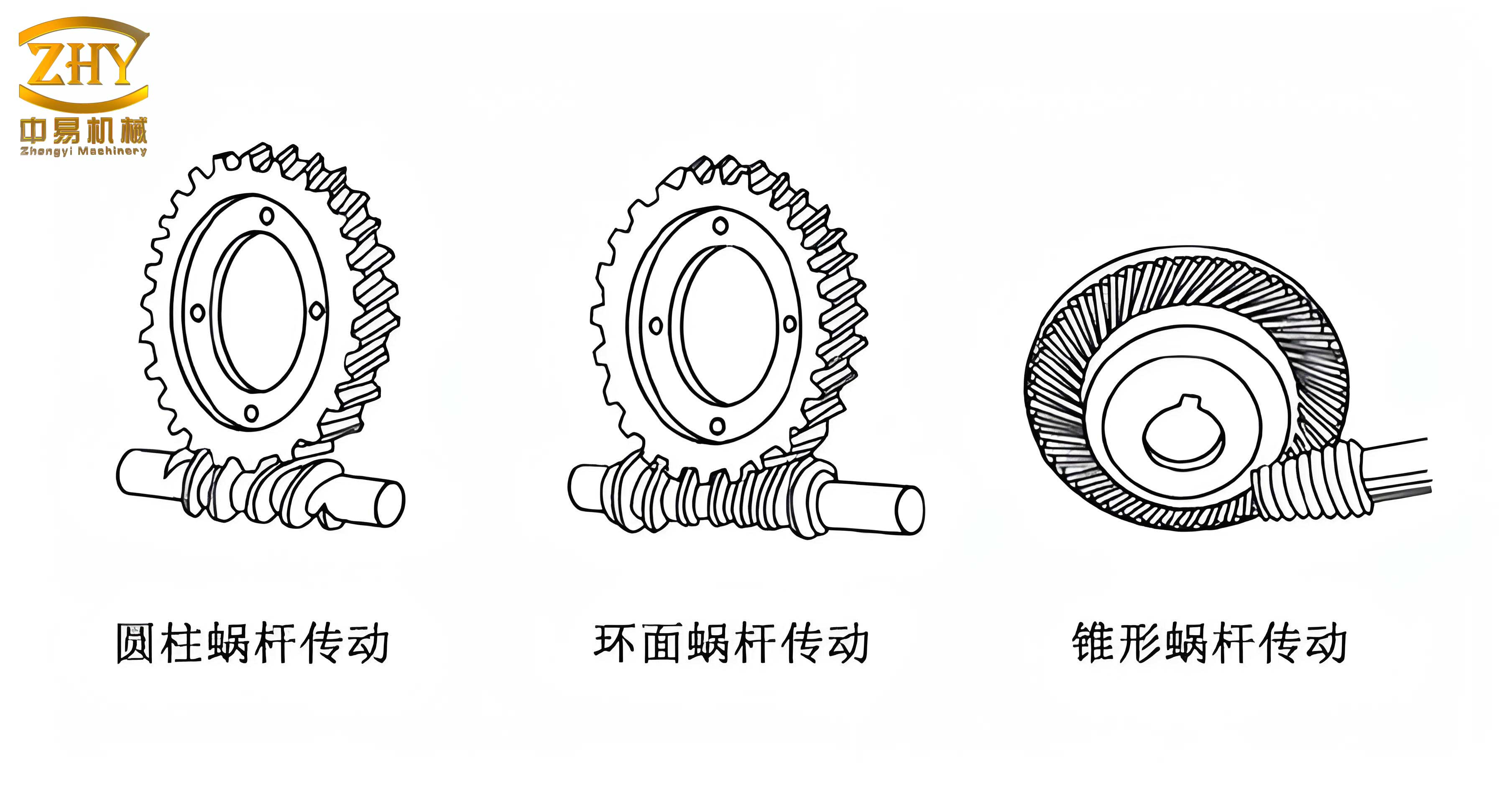
Screw gears, as shown in the image, have intricate geometries that demand careful detailing in drawings. Parameterized drawing technology simplifies this by automating the generation of such views based on input parameters.
Arrow drawing is essential for indicating features like fillet radii or diameters in screw gear drawings. I developed a subroutine ARROW that takes arrowhead and arrowtail coordinates as input. For example, to label the outside diameter of a screw gear, I calculate the arrow points based on the gear’s pitch circle and call ARROW to draw it. The subroutine handles arrowhead orientation and size, ensuring consistency across the drawing. The mathematical basis for arrow calculation involves vector direction: given arrowtail point $(x_t, y_t)$ and arrowhead point $(x_h, y_h)$, the arrowhead shape is derived from the direction vector $\vec{d} = (x_h – x_t, y_h – y_t)$. This is particularly useful for screw gears where arrows point to critical dimensions like throat diameters or root circles.
Block processing techniques greatly enhance efficiency in screw gear drawings. Common elements, such as gear tooth profiles or keyways, are defined as blocks using a subroutine BLOCKDEF, which saves them with a base point and a bounding window. Later, these blocks can be inserted at desired locations using BLOCKINS. This is invaluable for screw gear assemblies, where repeated features occur. For instance, I define a block for a standard screw gear tooth and insert it multiple times around the pitch circle, adjusting for the number of teeth. This modular approach also simplifies adding hatching to complex areas; by inserting blocks after hatching, interference is avoided. Below is a formula for calculating insertion points for tooth blocks in a screw gear:
$$ \theta_k = \frac{2\pi}{z} \cdot k, \quad x_k = r \cos(\theta_k), \quad y_k = r \sin(\theta_k) $$
where $z$ is the number of teeth, $r$ is the pitch radius, and $k$ ranges from 0 to $z-1$. Each $(x_k, y_k)$ serves as an insertion point for the tooth block, automating the drawing of screw gear teeth.
To illustrate the practical application, I developed a parameterized drawing software specifically for screw gears. This software accepts inputs such as module, pressure angle, lead angle, and material specifications, then generates complete工作图 including views, sections, and dimensions. For example, given a module $m=4$, worm threads $z_1=2$, and gear teeth $z_2=30$, the software calculates all dimensions and produces a drawing with annotated details. The table below shows sample calculations for such a screw gear:
| Parameter | Symbol | Value | Formula |
|---|---|---|---|
| Worm Pitch Diameter | $d_1$ | 8 mm | $d_1 = m \cdot z_1 = 4 \cdot 2$ |
| Gear Pitch Diameter | $d_2$ | 120 mm | $d_2 = m \cdot z_2 = 4 \cdot 30$ |
| Center Distance | $a$ | 64 mm | $a = \frac{d_1 + d_2}{2} = \frac{8 + 120}{2}$ |
| Lead Angle | $\gamma$ | 14.04° | $\tan \gamma = \frac{m \cdot z_1}{d_1}$ |
Using these values, the software computes coordinates for drawing points. For instance, the worm thread profile is generated using parametric equations based on the lead angle. The drawing process then calls subroutines for lines, arcs, and dimensions, ensuring that all features of the screw gears are accurately represented.
In terms of implementation, I have integrated error-checking mechanisms to handle invalid parameters for screw gears. For example, if the module is too small for the desired center distance, the software prompts the user to adjust inputs. This robustness is crucial for production environments where screw gears must meet strict tolerances. Additionally, the software supports multiple screw gear types, such as cylindrical or double-enveloping worms, by adjusting calculation algorithms accordingly.
Another key technique is the use of layering to organize screw gear drawings. Different layers are assigned for outlines, dimensions, hatching, and centerlines. This allows for easy editing and plotting control. When generating parameterized drawings for screw gears, I automatically assign entities to layers based on their function, improving readability and compliance with drafting standards.
Formula-driven drawings are central to parameterization. For screw gears, I derive all drawing entities from mathematical models. For example, the tooth profile of a screw gear can be approximated using involute equations or more complex curves based on gear theory. The general involute equation for a gear tooth is:
$$ x = r_b (\cos(\theta) + \theta \sin(\theta)), \quad y = r_b (\sin(\theta) – \theta \cos(\theta)) $$
where $r_b$ is the base radius and $\theta$ is the roll angle. For screw gears, this is adapted to account for the helix angle. By coding these equations into the drawing software, the tooth shape is generated dynamically, ensuring accuracy for any screw gear configuration.
Dimensioning challenges in screw gears often involve radial and axial dimensions. To address this, I use a combination of datum referencing and intelligent placement algorithms. For instance, axial dimensions along the worm shaft are referenced from a shoulder or end face, while radial dimensions are referenced from the centerline. The software checks for dimension clashes and adjusts positions automatically, or flags them for manual review. This is especially important for screw gears with tight spaces, such as those in compact drives.
Hatching cross-sections in screw gear drawings can be tricky due to irregular shapes. My solution involves defining the boundary of the cross-section as a polygon, then using a hatching subroutine that fills the area with lines at a specified angle and spacing. For screw gears, this is often applied to section views showing tooth engagement or hub details. The hatching parameters are derived from material standards, ensuring that drawings convey proper manufacturing instructions.
Block insertion is further enhanced with transformation options like rotation and scaling. When inserting a tooth block for a screw gear, I apply a rotation equal to the tooth angle $\theta_k$ to align it correctly on the pitch circle. This dynamic transformation ensures that the screw gear drawing is geometrically precise. The subroutine BLOCKINS accepts rotation and scale factors, making it versatile for various screw gear elements.
In conclusion, parameterized drawing technology for screw gears represents a significant advancement in mechanical design automation. By implementing techniques such as datum-based dimensioning, precise annotation placement, arrow drawing, and block processing, I have created a system that generates production-ready drawings efficiently. These methods ensure that screw gear drawings are accurate, consistent, and adaptable to design changes. The principles discussed here extend beyond screw gears to other mechanical components, offering a blueprint for developing robust CAD tools. As I continue to refine this technology, I aim to incorporate AI-driven optimization for screw gear designs, further enhancing their performance and manufacturability. The future of parameterized drawing for screw gears looks promising, with potential integrations into digital twin and Industry 4.0 frameworks, enabling smarter and more connected manufacturing processes.