In order to better judge the contact state and stress condition during the spiral bevel gear meshing process and analyze the stress transmission process, the transient analysis of the spiral bevel gear meshing state is carried out with the help of the finite element analysis software ANSYS to obtain the data results that are relatively close to the actual working conditions.
The non-contact area of spiral bevel gear tooth surface is considered as the initial state of transient simulation, that is, it needs to be impacted before contact, which may be more in line with the actual situation of spiral bevel gear operation. Firstly, a group of spiral bevel gears of a certain type are constructed and different meshing conditions are established. At the same time, the finite element analysis software ANSYS is used to conduct transient analysis on them and analyze their stress conditions under different meshing conditions.
| Driving wheel | Driven wheel | |
| Number of teeth | 10 | 37 |
| Module (mm) | 9.73 | 9.73 |
| Tooth surface width (mm) | 59.48 | 54.00 |
| Outer taper distance (mm) | 194.33 | 189.22 |
| Normal stress angle | 22°54 | 22°06 |
| Axis intersection angle | 90°00 | 90°00 |
| Helical angle | 17°34 | 72°02 |
| Rotation direction | Left-handed | Dextral rotation |
The basic parameters of the selected spiral bevel gear set are shown in Table 1 below. According to the use of spiral bevel gears, 20CrMnTi is often selected as the material of spiral bevel gears due to its large load value. The material properties are shown in Table 2.
| Material Science | Modulus of elasticity (GPa) | Poisson’s ratio | Density (kg/m3) |
| 20CrMnTi | 206 | 0.25 | 7800 |
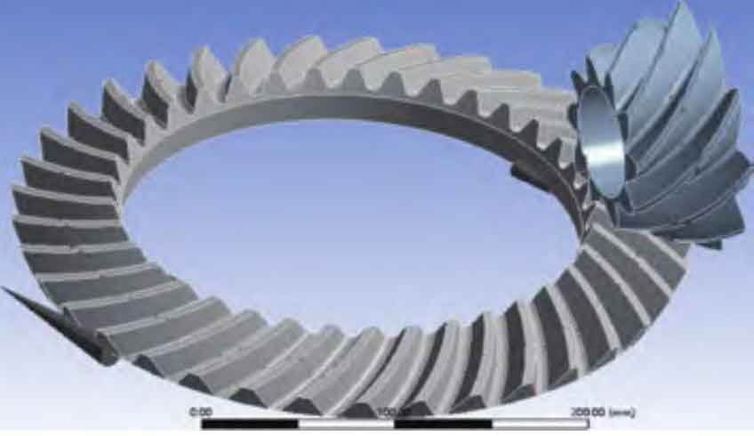
When assembling spiral bevel gears, first determine the shaft spacing when the shafts of the two spiral bevel gears are perpendicular, and then design the position of the driving gear based on the driven gear. After the positions of the two spiral bevel gears are determined, rotate the gear to achieve meshing. The spiral bevel gear after meshing is as shown in the figure.