
In the pursuit of high-precision and high-efficiency finishing of hardened gears, traditional gear honing processes often encounter significant limitations. These include rapid loading and wear of the honing tool, suboptimal surface integrity, and constraints on achievable material removal rates. My research focuses on overcoming these challenges by integrating ultrasonic vibration into the gear honing process. The introduction of high-frequency, low-amplitude oscillations fundamentally alters the cutting mechanics. It reduces the effective coefficient of friction, facilitates chip evacuation—thereby minimizing tool loading—and can significantly lower the honing forces. This synergy leads to improved surface finish, enhanced geometrical accuracy, and extended tool life, presenting a compelling advancement in precision gear manufacturing technology.
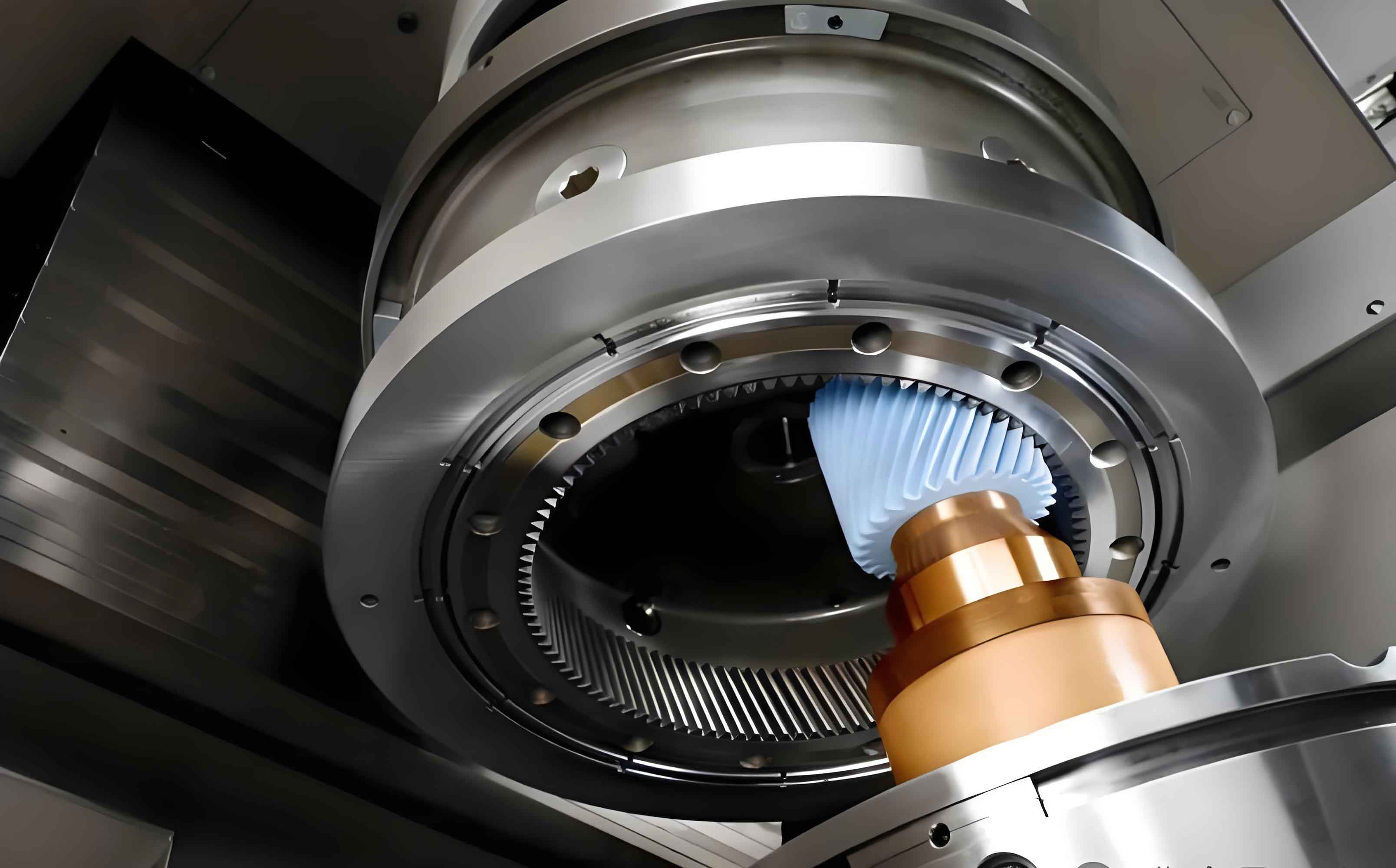
The efficacy of ultrasonic vibration-assisted gear honing is critically dependent on the performance of the ultrasonic vibration system. This system typically comprises an ultrasonic generator, a piezoelectric transducer, and an acoustic transformer, often referred to as a horn or concentrator. In the context of gear honing, the transformer has a dual role: it mechanically amplifies the displacement amplitude generated by the transducer and, most importantly, it serves as the fixture for the workpiece gear. Therefore, the design of this transformer is not merely about a standalone resonant horn; it is the design of a coupled system—the gear-transformer assembly. The dynamic interaction between the elastic body of the gear and the transformer rod dictates the final resonant characteristics of the entire system. A poorly designed assembly will fail to resonate at the desired ultrasonic frequency (typically 18-40 kHz) with the appropriate longitudinal-bending modal shape, rendering the ultrasonic assistance ineffective.
The primary challenge lies in the variability introduced by the workpiece gear. Each gear, with its unique set of parameters—module, number of teeth, face width, and material—acts as a distinct dynamic mass and stiffness element attached to the end of the transformer. A transformer designed for one specific gear will not necessarily resonate correctly with another. Given the vast number of potential gear configurations in industrial applications, designing a unique transformer empirically for each one is impractical. This necessitates a robust, theoretically grounded, and computationally efficient design methodology. My approach involves a closed-loop process of analytical modeling, parametric computer-aided design (CAD), and finite element analysis (FEA) verification, enabling the rapid development and optimization of ultrasonic transformers for diverse gear honing applications.
Theoretical Foundation for Gear-Transformer Coupled System Design
The foundation for designing an effective ultrasonic system for gear honing begins with modeling the gear not as a rigid mass but as an elastic disk capable of complex vibrations. The transformer is modeled as a continuous rod with varying cross-section. The goal is to derive the longitudinal vibration characteristics of the coupled system. For a stepped or conical transformer rod, the one-dimensional wave equation governs its longitudinal vibration. For a segment with constant cross-sectional area \( A(x) \) and material density \( \rho \), the equation of motion is:
$$ \frac{\partial}{\partial x} \left( E A(x) \frac{\partial u(x,t)}{\partial x} \right) = \rho A(x) \frac{\partial^2 u(x,t)}{\partial t^2} $$
where \( u(x,t) \) is the longitudinal displacement, \( E \) is the Young’s modulus, and \( x \) is the spatial coordinate along the rod’s axis. The solution for harmonic vibration \( u(x,t) = U(x)e^{j\omega t} \) leads to an expression for the displacement and force distribution along the rod. For a conical horn, the cross-sectional area varies as \( A(x) = A_1 (1 – \alpha x)^2 \), where \( A_1 \) is the area at the large end and \( \alpha \) is the taper factor. The resonance condition is determined by applying boundary conditions: at the large end (x=0), it is connected to the transducer (often modeled as a velocity or impedance boundary), and at the small end (x=L), it is coupled to the gear.
The gear is treated as a thin elastic disk for initial approximation. Its axial (longitudinal) vibration is coupled to the transformer’s longitudinal motion, while its in-plane bending vibrations can also be excited. The coupling between the transformer tip and the gear is modeled through continuity of displacement and force (stress) at their interface. This “stress coupling” condition is crucial. It states that at the junction:
$$ U_{rod}(L) = U_{gear}(0) $$
$$ E_{rod} A_{rod}(L) \frac{dU_{rod}(L)}{dx} = -F_{gear} $$
where \( F_{gear} \) represents the reaction force from the gear’s base due to its vibration. This force is derived from the gear’s own dynamic equations. By combining the general solutions for the transformer’s wave equation with the dynamic impedance of the gear disk, a characteristic equation for the entire system’s natural frequency \( \omega \) can be established. Solving this transcendental equation yields the theoretical resonant frequency and the corresponding mode shape. This analytical model allows for a non-resonant design of the transformer itself; the rod is designed not to resonate alone at the target frequency but to do so only when coupled with its specific gear, ensuring optimal energy transfer into the workpiece during gear honing.
Parametric Modeling Framework for Variable Gear Configurations
To translate the theoretical design into a manufacturable model and to enable rapid adaptation for different gears, a parametric modeling strategy is essential. I employ a feature-based, parametric CAD environment (exemplified by software like PTC Creo/Pro-Engineer) to create a fully associative model of the gear-transformer assembly. The core principle is to define a set of master parameters that drive all geometric features.
The parameter set is divided into two primary groups: Gear Parameters and Transformer Parameters.
| Parameter Group | Symbol | Description | Typical Value/Range |
|---|---|---|---|
| Gear Parameters | \( m \) | Module | 1.5 – 4 mm |
| \( z \) | Number of Teeth | 20 – 60 | |
| \( \alpha \) | Pressure Angle | 20° | |
| \( b \) | Face Width | 10 – 30 mm | |
| \( x \) | Profile Shift Coefficient | -0.5 – +0.5 | |
| \( h_a^* \) | Addendum Coefficient | 1.0 | |
| \( c^* \) | Dedendum Clearance Coefficient | 0.25 | |
| \( \rho_{gear} \) | Material Density | 7850 kg/m³ (Steel) | |
| Transformer Parameters | \( D_{large} \) | Large End Diameter | Match transducer (e.g., 70 mm) |
| \( D_{small} \) | Small End Diameter | Constraint by gear bore (e.g., 20 mm) | |
| \( D_{hole} \) | Central Cooling Hole Diameter | 6 – 12 mm | |
| \( L_{rod} \) | Theoretical Resonant Length | ~λ/2 (e.g., 150-220 mm for steel at 20 kHz) | |
| \( Taper \) | Profile Taper Angle | Calculated from end diameters and length | |
| \( \rho_{rod} \) | Material Density (e.g., Titanium, Steel) | 4500 kg/m³ or 7850 kg/m³ |
These parameters are not static; they are linked through “relations” or “equations.” For the gear, the fundamental geometric relations are programmed:
$$ \text{Pitch Diameter: } d = m \cdot z $$
$$ \text{Base Diameter: } d_b = d \cdot \cos(\alpha) $$
$$ \text{Addendum: } h_a = (h_a^* + x) \cdot m $$
$$ \text{Dedendum: } h_f = (h_a^* + c^* – x) \cdot m $$
$$ \text{Tip Diameter: } d_a = d + 2h_a $$
$$ \text{Root Diameter: } d_f = d – 2h_f $$
The most critical aspect is the generation of the involute tooth profile. This is achieved by programming the parametric equation of an involute curve into the CAD system. In a Cartesian coordinate system with the origin at the gear center, the involute coordinates are given as a function of a parameter \( t \):
$$ r_b = \frac{d_b}{2} $$
$$ \theta = t \cdot \theta_{max} \quad \text{(where } \theta_{max} \text{ is sufficient to span the tooth flank, e.g., 60°)} $$
$$ x_{inv}(\theta) = r_b (\cos\theta + \theta \sin\theta) $$
$$ y_{inv}(\theta) = r_b (\sin\theta – \theta \cos\theta) $$
This curve is generated, mirrored about a plane rotated by \( 360^\circ / (4z) \) to create one tooth slot, and then patterned around the axis \( z \) times to complete the gear model. The transformer body, typically a conical or stepped horn, is created using a revolve feature driven by its parameters \( D_{large} \), \( D_{small} \), and \( L_{rod} \). The central hole is subtracted via an extrusion. The gear is then assembled concentrically to the small end of the transformer, completing the parametric assembly. Changing any master parameter (e.g., gear module \( m \), number of teeth \( z \), or transformer length \( L_{rod} \)) and triggering a “regenerate” command automatically updates the entire 3D geometry accurately and instantly. This library-based approach is indispensable for the iterative design process required in ultrasonic gear honing system development.
Finite Element Modal Analysis for Design Validation and Optimization
While the analytical model provides a first estimate, the complexities of a real 3D gear geometry—with its discontinuous tooth structure and stress concentrations—make Finite Element Analysis (FEA) the indispensable tool for validation and precise frequency prediction. The parametrically generated CAD model serves as the perfect starting point. Using a direct geometry associativity interface (like the Pro/ENGINEER-ANSYS connection or standard STEP/IGES transfer), the model is imported into an FEA pre-processor without any loss of geometric detail.
The analysis type is a modal analysis, aiming to find the natural frequencies and corresponding mode shapes of the free-free or lightly constrained gear-transformer assembly. The key steps in the FEA workflow are as follows:
1. Material Property Assignment: Both the transformer and the gear are assigned linear elastic, isotropic material properties. For steel: Young’s Modulus \( E = 2.1 \times 10^{11} \) Pa, Poisson’s ratio \( \nu = 0.3 \), Density \( \rho = 7850 \) kg/m³. For titanium alloy (sometimes used for transformers due to its high strength-to-weight ratio and good acoustic properties): \( E \approx 1.1 \times 10^{11} \) Pa, \( \nu = 0.34 \), \( \rho = 4500 \) kg/m³.
2. Meshing Strategy: Given the complex gear teeth, an automated tetrahedral meshing algorithm (using 10-node quadratic tetrahedral elements, e.g., SOLID187 in ANSYS) is often most practical. A curvature-based mesh refinement is applied to the tooth flanks and fillets to capture stress gradients and geometric details accurately. A mesh convergence study is performed to ensure the results (especially the target resonant frequency) are independent of element size. A typical high-fidelity model for a medium-sized gear and transformer can have 500,000 to 1.5 million nodes.
3. Boundary Conditions and Solving: For modal analysis of a free vibration system, no constraints are applied in theory. However, to avoid rigid body modes (six zero-frequency modes), it is common to apply very soft spring supports at strategic points or to use the solver’s built-in function to eliminate them. The Block Lanczos eigenvalue extraction algorithm is highly efficient for large models and is set to extract modes within a frequency range of interest, e.g., 10 kHz to 35 kHz.
4. Post-Processing and Target Mode Identification: The solver returns a list of natural frequencies and their associated mode shapes. The critical task is to identify the mode that corresponds to the desired operating condition for ultrasonic gear honing: primarily, a strong longitudinal vibration of the transformer coupled with a coherent, in-phase bending or axial vibration of the gear body. This mode ensures the ultrasonic energy is effectively transmitted to the gear-honing tool interface. Displacement contour plots are analyzed to confirm this. The target resonant frequency \( f_{FEA} \) from the simulation is then compared to the design frequency \( f_{design} \) (typically the ultrasonic generator frequency, e.g., 20 kHz ± 0.5 kHz).
To illustrate the effect of gear parameters on the system dynamics, consider the following table summarizing FEA results for four different gear configurations coupled to a transformer initially designed for Gear 1. The transformer’s large end diameter is 70 mm, small end diameter is 20 mm, central hole is 12 mm, and its initial length was designed analytically for a target frequency of 20 kHz with Gear 1.
| Gear ID | Module (mm) | Teeth (z) | Face Width (mm) | Pitch Dia. (mm) | FEA Resonant Freq. (kHz) | Deviation from 20 kHz | Primary Vibration Mode Observed |
|---|---|---|---|---|---|---|---|
| Gear 1 | 3.0 | 36 | 12 | 108 | 19.12 | -0.88 kHz | Clean longitudinal rod + gear axial |
| Gear 2 | 2.5 | 44 | 15 | 110 | 21.45 | +1.45 kHz | Longitudinal rod with mild gear bending |
| Gear 3 | 2.0 | 26 | 20 | 52 | 17.03 | -2.97 kHz | Mixed rod longitudinal/gear complex bending |
| Gear 4 | 4.0 | 25 | 10 | 100 | 20.87 | +0.87 kHz | Longitudinal rod + gear axial |
The results clearly demonstrate the significant influence of the gear’s dynamic mass and stiffness. Gear 3, with a smaller pitch diameter but greater face width (higher mass and stiffness), lowers the frequency substantially. Gear 2, with more teeth and a similar pitch diameter but different modal characteristics, raises it. Only Gears 1 and 4 produce frequencies close to the target 20 kHz with the desired mode shape, and even they require fine-tuning. This table underscores why a universal transformer is ineffective for precision ultrasonic gear honing.
Iterative Optimization and Sensitivity Analysis
The FEA result provides the feedback needed for optimization. If the resonant frequency \( f_{FEA} \) deviates from the target \( f_{target} \), the transformer’s length \( L_{rod} \) is the most sensitive parameter for adjustment. The relationship between length and frequency for a longitudinal resonator is approximately inverse. A simple corrective rule can be derived:
$$ \Delta L \approx -L_{rod} \cdot \frac{\Delta f}{f_{FEA}} $$
where \( \Delta f = f_{FEA} – f_{target} \). For example, if \( f_{FEA} = 19.12 \) kHz for a 200 mm long rod and \( f_{target} = 20.00 \) kHz, then \( \Delta f = -0.88 \) kHz. The required length change is approximately:
$$ \Delta L \approx -200 \text{ mm} \cdot \frac{-0.88 \text{ kHz}}{19.12 \text{ kHz}} \approx +9.2 \text{ mm} $$
Thus, the rod length should be increased to about 209.2 mm. This new value is updated in the parametric CAD model as \( L_{rod} \), the model is regenerated, re-meshed, and re-analyzed in FEA. This iterative loop typically converges to a design meeting the frequency tolerance (e.g., ±200 Hz) within 2-3 cycles.
Beyond length, other parameters can be optimized for different objectives. The central hole diameter \( D_{hole} \) affects the stress distribution and amplification factor. The taper profile influences the stress nodes and amplification. A multi-objective optimization can be set up using FEA-based design of experiments (DOE) or response surface methodology (RSM). Objectives might include:
- Maximizing the displacement amplification factor \( M \) at the gear face: \( M = \frac{U_{gear}}{U_{transducer}} \).
- Minimizing the maximum stress \( \sigma_{max} \) under dynamic loading to ensure infinite fatigue life.
- Achieving a target resonant frequency \( f_{target} \).
- Minimizing the transverse vibration component at the gear to ensure pure axial excitation for gear honing.
The parametric model is the engine for this optimization. Each design variable (\( L_{rod}, D_{small}, Taper, D_{hole} \)) is defined as a parameter. The FEA solver is scripted to vary these parameters, solve the modal and harmonic analyses, and extract the response values (frequency, amplitude, stress). The process can be summarized by the following optimization formulation:
Find design vector \( \mathbf{X} = [L_{rod}, D_{small}, Taper]^T \) to:
Minimize: \( |f(\mathbf{X}) – f_{target}| + w_1 \cdot \frac{1}{M(\mathbf{X})} + w_2 \cdot \sigma_{max}(\mathbf{X}) \)
Subject to: \( \sigma_{max}(\mathbf{X}) \leq \sigma_{allowable} \), \( L_{min} \leq L_{rod} \leq L_{max} \), etc.
Where \( w_1, w_2 \) are weighting factors.
This integrated CAD-FEA optimization framework drastically reduces the time from concept to a validated, performance-optimized design for ultrasonic gear honing transformers, making the technology adaptable and viable for low-volume, high-mix production environments common in precision engineering.
Conclusion and Technological Impact
The integration of ultrasonic vibration into gear honing represents a significant leap forward in finishing technology for high-performance gear components. The core enabler of this technology is the reliable and adaptable design of the acoustic transformer assembly. The methodology presented—combining theoretical coupled-system dynamics, parametric feature-based CAD modeling, and iterative FEA validation/optimization—forms a robust, systematic engineering pipeline.
This approach directly addresses the primary challenge of component variability in gear honing. It moves away from ad-hoc, trial-and-error horn design towards a deterministic, simulation-driven process. The parametric model library allows for the rapid generation and analysis of candidate designs for any given gear specification. The FEA not only verifies the resonant frequency but also provides critical insights into stress distribution, mode shape purity, and potential areas of fatigue failure, enabling the design of durable and efficient systems.
The ultimate impact is on the gear honing process itself: reduced honing forces lead to less tool wear and deflection, improved chip evacuation minimizes loading and scratching, and the superimposed ultrasonic energy can enhance surface metamorphosis, potentially leading to better fatigue resistance of the finished gear tooth flanks. By providing a clear pathway to design the heart of the ultrasonic system, this work helps to mature ultrasonic vibration-assisted gear honing from a laboratory concept into a viable, high-precision manufacturing solution for the automotive, aerospace, and energy sectors, where the quality of gears is paramount.