
I have developed a parametric design and optimization system for straight bevel gears by using Visual Lisp inside AutoCAD. The motivation for this development is straightforward: straight bevel gears are widely used in航空? No Chinese. Let me restart. The motivation for this development is straightforward: straight bevel gears are widely used in aerospace, automotive, and heavy machinery transmission systems because they can change the direction of motion, maintain a high contact ratio, and transmit motion smoothly. However, the design of straight bevel gears involves many parameters, long calculation chains, and repeated manual checks. In practical engineering design, these characteristics make the process time-consuming and prone to error. I therefore decided to build a modular program that can perform design calculation, strength validation, parametric drawing, and parameter optimization within a single AutoCAD-based environment.
The system is written in Visual Lisp, which is embedded in AutoCAD and can directly call almost all AutoCAD commands, system variables, and dialog boxes. With this approach, I can change a file name, assign different numerical values to the same set of parameters, and generate several or even dozens of drawings without repeating the interactive drawing work. The result is a practical method for reducing repetitive labor and improving design efficiency for straight bevel gears and similar products.
I organized the entire development around four functional goals. The first goal is calculation: the program accepts the basic parameters of straight bevel gears and computes the required geometric and strength parameters according to predefined algorithms. The second goal is process prompting: the program gives appropriate messages when input data are outside a recommended range or when a strength check fails. The third goal is data storage: the program saves the design parameters in a structured format so that they can be queried and reused. The fourth goal is drawing: the program generates a two-dimensional drawing from the final design results of straight bevel gears.
| Module | Main function | Primary output |
|---|---|---|
| Initial parameter input | Read gear ratio, torque, speed, material limits, and preliminary factors | Validated initial parameter list |
| Geometric calculation | Compute cone angles, pitch diameters, cone distance, face width, addendum, dedendum, tip angles, and root angles | Complete geometric parameter set for straight bevel gears |
| Contact fatigue check | Compute contact stress and contact safety factor | Contact stress, allowable contact stress, safety margin |
| Bending fatigue check | Compute tooth root bending stress and bending safety factor | Bending stress, allowable bending stress, safety margin |
| Parametric drawing | Create layers, line types, line weights, polylines, and dimensions | Two-dimensional drawing of straight bevel gears |
| Optimization | Minimize total gear volume under geometry and strength constraints | Optimized tooth number, module, face width coefficient |
For the initial input module, I used an AutoCAD dialog box to collect the preliminary design data. The initial parameters include the pinion torque, pinion speed, preliminary safety factor, gear speed, contact fatigue limit, and load factor. A representative initial data set for straight bevel gears is shown below. I used this data set to test the calculation and validation modules before moving to optimization.
| Parameter | Symbol | Value | Unit |
|---|---|---|---|
| Pinion torque | \(T_1\) | 140.0 | N·m |
| Pinion speed | \(n_1\) | 960.0 | r/min |
| Preliminary safety factor | \(s_H\) | 1.1 | — |
| Gear speed | \(n_2\) | 325.0 | r/min |
| Contact fatigue limit | \(\sigma_{H\lim}\) | 1300.0 | N/mm² |
| Load factor | \(K\) | 1.5 | — |
The geometric calculation module is the core of the parametric design process for straight bevel gears. I first compute the transmission ratio and the pitch cone angles. For an orthogonal straight bevel gear pair, the shaft angle is \(90^\circ\). The transmission ratio is obtained from the speed ratio and the tooth numbers:
$$
u = \frac{n_1}{n_2} = \frac{z_2}{z_1}
$$
The pitch cone angles are then calculated as follows:
$$
\delta_1 = \arctan\left(\frac{z_1}{z_2}\right)
$$
$$
\delta_2 = 90^\circ – \delta_1
$$
After the cone angles are known, I calculate the external pitch diameters and the external cone distance. For straight bevel gears, the external module \(m_e\) is usually used for the large end. The external pitch diameters are:
$$
d_{e1} = m_e z_1
$$
$$
d_{e2} = m_e z_2
$$
The external cone distance is:
$$
R_e = \frac{m_e}{2}\sqrt{z_1^2+z_2^2}
$$
The face width is obtained from the face width coefficient \(\phi_R\):
$$
b = \phi_R R_e
$$
For straight bevel gears, I use the common addendum and dedendum relationships:
$$
h_a = m_e
$$
$$
h_f = 1.2 m_e
$$
The tip diameters and root diameters at the large end are:
$$
d_{ae1} = d_{e1} + 2h_a\cos\delta_1
$$
$$
d_{ae2} = d_{e2} + 2h_a\cos\delta_2
$$
$$
d_{fe1} = d_{e1} – 2h_f\cos\delta_1
$$
$$
d_{fe2} = d_{e2} – 2h_f\cos\delta_2
$$
The tip angle and root angle are computed from the addendum and dedendum relative to the cone distance:
$$
\theta_a = \arctan\left(\frac{h_a}{R_e}\right)
$$
$$
\theta_f = \arctan\left(\frac{h_f}{R_e}\right)
$$
The tip cone angles and root cone angles of the two straight bevel gears are:
$$
\delta_{a1} = \delta_1 + \theta_a
$$
$$
\delta_{f1} = \delta_1 – \theta_f
$$
$$
\delta_{a2} = \delta_2 + \theta_a
$$
$$
\delta_{f2} = \delta_2 – \theta_f
$$
I summarize the geometric relationships used by the program in the following table. These relationships allow the Visual Lisp routines to compute a complete set of geometry from a small number of initial parameters for straight bevel gears.
| Geometric item | Expression | Remarks |
|---|---|---|
| Transmission ratio | \(u = z_2/z_1 = n_1/n_2\) | Speed ratio and tooth ratio |
| Pinion pitch cone angle | \(\delta_1 = \arctan(z_1/z_2)\) | Orthogonal shaft angle |
| Gear pitch cone angle | \(\delta_2 = 90^\circ – \delta_1\) | Orthogonal shaft angle |
| External pitch diameter | \(d_{e1}=m_e z_1,\ d_{e2}=m_e z_2\) | Large end |
| External cone distance | \(R_e = \frac{m_e}{2}\sqrt{z_1^2+z_2^2}\) | Large end |
| Face width | \(b = \phi_R R_e\) | Usually \(0.25 \le \phi_R \le 0.33\) |
| Addendum | \(h_a = m_e\) | Standard proportion |
| Dedendum | \(h_f = 1.2m_e\) | Standard proportion |
| Tip diameter | \(d_{ae}=d_e+2h_a\cos\delta\) | Large end |
| Root diameter | \(d_{fe}=d_e-2h_f\cos\delta\) | Large end |
| Tip angle | \(\theta_a=\arctan(h_a/R_e)\) | Used for tip cone angle |
| Root angle | \(\theta_f=\arctan(h_f/R_e)\) | Used for root cone angle |
In the actual implementation, the geometric calculation module writes each result to a global parameter list. The drawing module and the strength check modules then read from that list. This design avoids repeated input and keeps the data consistent across all stages of the design of straight bevel gears.
Once the geometry is available, I perform the contact fatigue strength check. For orthogonal straight bevel gears with a shaft angle of \(90^\circ\), I use the contact stress relationship shown below. The contact stress depends on the tangential force, the mean pitch diameter, the face width, the transmission ratio, and a set of influence factors.
$$
\sigma_H = \sqrt{\frac{K_A K_V K_{H\beta} K_{H\alpha} F_t}{d_{m1} l_b m}} \cdot \frac{\sqrt{u^2+1}}{u} Z_M Z_{M-B} Z_H Z_E Z_{LS} Z_\beta Z_K \le \sigma_{HP}
$$
Here, \(K_A\) is the application factor, \(K_V\) is the dynamic factor, \(K_{H\beta}\) is the face load factor, and \(K_{H\alpha}\) is the transverse load factor. The factors \(Z_M\), \(Z_{M-B}\), \(Z_H\), \(Z_E\), \(Z_{LS}\), \(Z_\beta\), and \(Z_K\) represent the material, midpoint, zone, elasticity, load sharing, helix angle, and bevel gear influences, respectively. The allowable contact stress is calculated from the contact fatigue limit and the life, lubrication, size, and work hardening factors:
$$
\sigma_{HP} = \frac{\sigma_{H\lim} Z_N Z_{LVR} Z_X Z_W}{S_{H\min}}
$$
The contact safety factor is then:
$$
S_H = \frac{\sigma_{H\lim} Z_N Z_{LVR} Z_X Z_W}{\sigma_H} \ge S_{H\min}
$$
The tangential force at the mean pitch diameter is obtained from the pinion torque:
$$
F_t = \frac{2000 T_1}{d_{m1}}
$$
The mean pitch diameter of the pinion is related to the external pitch diameter and the face width coefficient:
$$
d_{m1} = d_{e1}(1-0.5\phi_R)
$$
The mean module is:
$$
m_m = m_e(1-0.5\phi_R)
$$
I used a dialog box to collect the contact check parameters. The following table lists a representative set of contact fatigue input values for the straight bevel gears in my test case.
| Parameter | Symbol | Value |
|---|---|---|
| Application factor | \(K_A\) | 1.25 |
| Dynamic factor | \(K_V\) | 1.08 |
| Face load factor | \(K_{H\beta}\) | 1.10 |
| Transverse load factor | \(K_{H\alpha}\) | 1.00 |
| Zone factor | \(Z_H\) | 2.50 |
| Elasticity factor | \(Z_E\) | 189.80 |
| Load sharing factor | \(Z_{LS}\) | 1.00 |
| Helix angle factor | \(Z_\beta\) | 1.00 |
| Bevel gear factor | \(Z_K\) | 0.80 |
| Lubrication factor | \(Z_{LVR}\) | 0.95 |
| Size factor | \(Z_X\) | 1.00 |
| Work hardening factor | \(Z_W\) | 1.00 |
| Minimum safety factor | \(S_{H\min}\) | 1.10 |
| Contact fatigue limit | \(\sigma_{H\lim}\) | 1300.0 |
| Life factor | \(Z_N\) | 1.00 |
| Additional factor | \(F_1\) | 2.00 |
The bending fatigue strength check follows the same modular pattern. For straight bevel gears, I use the tooth root bending stress relationship shown below. The bending stress depends on the tangential force, the face width, the mean module, and the tooth form and load distribution factors.
$$
\sigma_F = \frac{K_A K_V K_{F\beta} K_{F\alpha} F_t}{b m_m} Y_{FS} Y_E Y_K Y_{LS} \le \sigma_{FP}
$$
In this expression, \(K_{F\beta}\) is the tooth root face load factor, \(K_{F\alpha}\) is the transverse load factor for bending, \(Y_{FS}\) is the composite tooth form factor, \(Y_E\) is the contact ratio factor, \(Y_K\) is the bevel gear factor, and \(Y_{LS}\) is the load sharing factor. The allowable bending stress is:
$$
\sigma_{FP} = \frac{\sigma_{FE} Y_{NT} Y_{\delta relT} Y_{R relT} Y_X}{S_{F\min}}
$$
The bending safety factor is therefore:
$$
S_F = \frac{\sigma_{FE} Y_{NT} Y_{\delta relT} Y_{R relT} Y_X}{\sigma_F} \ge S_{F\min}
$$
I collected the bending check parameters through a second dialog box. The table below shows the values I used for the initial validation of straight bevel gears.
| Parameter | Symbol | Value |
|---|---|---|
| Application factor | \(K_A\) | 1.25 |
| Dynamic factor | \(K_V\) | 1.045 |
| Face load factor | \(K_{H\beta e}\) | 1.10 |
| Tooth root face load factor | \(K_{F\beta}\) | 1.65 |
| Transverse load factor | \(K_{H\alpha}\) | 1.00 |
| Composite form factor, pinion | \(Y_{FS1}\) | 4.72 |
| Composite form factor, gear | \(Y_{FS2}\) | 4.20 |
| Size factor, gear | \(Y_{X2}\) | 1.00 |
| Contact ratio factor | \(\varepsilon_{va}\) | 1.746 |
| Load sharing factor | \(Z_{LS}\) | 1.00 |
| Life factor | \(Y_{NT}\) | 1.00 |
| Minimum safety factor | \(S_{F\min}\) | 1.40 |
| Bending fatigue limit | \(\sigma_{FE}\) | 630.0 |
| Relative notch sensitivity | \(Y_{\delta relT}\) | 1.00 |
| Relative surface condition | \(Y_{R relT}\) | 1.00 |
| Size factor, pinion | \(Y_{X1}\) | 1.00 |
After both strength checks pass, the program enters the parametric drawing stage. In Visual Lisp, I defined a set of user functions and stored them as an LSP file. The drawing procedure first determines the base point of the drawing, then computes the coordinates of each vertex of the straight bevel gears, and finally connects the vertices in the required order. I also define layers, line types, and line weights before drawing. This step is important because straight bevel gears have multiple circles, cone lines, and tooth profile elements that must be separated clearly in a two-dimensional drawing.
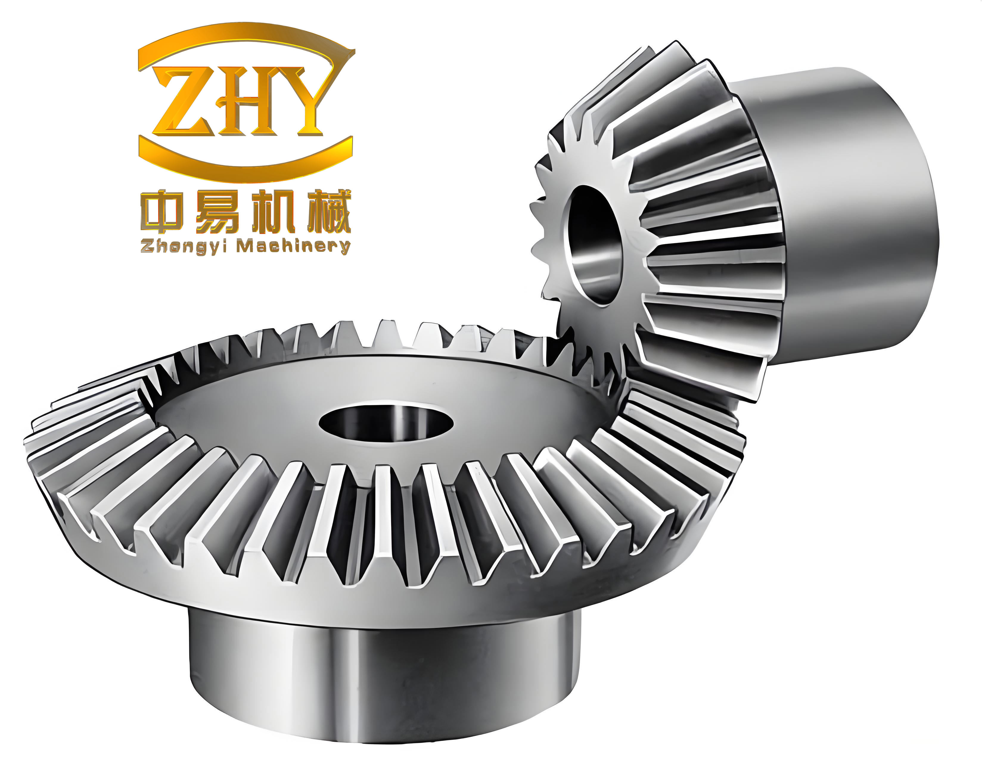
For the drawing module, I compute the large-end and small-end radii of the pitch circle, the tip circle, and the root circle. The large-end pitch radius of the pinion is:
$$
r_{e1} = \frac{d_{e1}}{2}
$$
The small-end pitch radius is obtained by linear scaling along the cone distance:
$$
r_{e1}’ = r_{e1}\frac{R_e-b}{R_e}
$$
The large-end tip radius and root radius are:
$$
r_{ae1} = r_{e1} + h_a\cos\delta_1
$$
$$
r_{fe1} = r_{e1} – h_f\cos\delta_1
$$
Similar expressions are used for the gear. I use these radii to construct the axial section of the straight bevel gears, and then I mirror or rotate the section to obtain the required two-dimensional representation. The following table summarizes the coordinate quantities used by the drawing routines.
| Drawing quantity | Expression | Purpose |
|---|---|---|
| Large-end pitch radius | \(r_e = d_e/2\) | Pitch circle in axial section |
| Small-end pitch radius | \(r_e’ = r_e(R_e-b)/R_e\) | Small-end pitch circle |
| Large-end tip radius | \(r_{ae} = r_e + h_a\cos\delta\) | Tip circle |
| Large-end root radius | \(r_{fe} = r_e – h_f\cos\delta\) | Root circle |
| Axial position of large end | \(x=0\) | Base reference |
| Axial position of small end | \(x=b\) | Face width reference |
The drawing module also inserts dimensions for the pitch diameter, tip diameter, face width, and cone distance. I use AutoCAD system variables to control the dimension style, text height, and arrow size. Because the drawing is generated from the parameter list, a change in the module, tooth number, or face width coefficient automatically updates the drawing of the straight bevel gears.
After the design and validation modules were working, I added an optimization module. The traditional design of straight bevel gears often relies on empirical parameter selection, repeated calculation, and manual checking. This approach is not always accurate and can lead to an oversized gear pair. I therefore formulated an optimization problem in which the objective is to minimize the total volume of the two gears. The volume is approximated by the volume between the large-end pitch circle and the small-end pitch circle, which is a conical frustum. The objective function is:
$$
V = V_1 + V_2 = \frac{\pi}{3} b \cos\delta_1 \left[ \left(\frac{m_e z_1}{2}\right)^2 + \left(\frac{m_e z_1 (R_e-b)}{2R_e}\right)^2 + \frac{m_e z_1}{2} \cdot \frac{m_e z_1 (R_e-b)}{2R_e} \right] + \frac{\pi}{3} b \cos\delta_2 \left[ \left(\frac{m_e z_2}{2}\right)^2 + \left(\frac{m_e z_2 (R_e-b)}{2R_e}\right)^2 + \frac{m_e z_2}{2} \cdot \frac{m_e z_2 (R_e-b)}{2R_e} \right]
$$
For the orthogonal straight bevel gears considered here, this expression can be reduced to a more compact form in terms of the transmission ratio, module, pinion tooth number, and face width coefficient:
$$
V = \frac{\pi}{8} u (u+1) m_e^3 z_1^2 \phi_R (1-\phi_R+\phi_R^3)
$$
The design variables are the pinion tooth number \(z_1\), the external module \(m_e\), and the face width coefficient \(\phi_R\). The constraints are based on avoiding undercut, keeping the face width within a recommended range, and ensuring that the module is suitable for power transmission. The pinion tooth number constraint is:
$$
z_{1\min} = \frac{2\cos\delta_1}{\sin\alpha}
$$
$$
13 \le z_1 \le 36
$$
The face width coefficient constraint is:
$$
\frac{1}{4} \le \phi_R \le \frac{1}{3}
$$
In most practical designs of straight bevel gears, I set the initial value of \(\phi_R\) to about 0.3 and allow the optimizer to adjust it slightly within the allowed range. The module constraint is:
$$
2 \le m_e \le 10
$$
$$
m_e(1-0.5\phi_R) \ge 1.5
$$
I used a random direction search method for the optimization of straight bevel gears. The procedure first fixes the tooth number, then adjusts the face width coefficient, and finally adjusts the module. At each step, the program evaluates the objective function and checks the constraints. If a candidate point violates a constraint, it is rejected. If the candidate point reduces the total volume and satisfies all constraints, it becomes the new base point. The search continues until the improvement becomes smaller than a specified tolerance.
| Quantity | Symbol | Initial design | Optimized design | Change |
|---|---|---|---|---|
| Pinion tooth number | \(z_1\) | 17 | 21 | +23.53% |
| External module | \(m_e\) | 4.5 | 3.5 | -22.22% |
| Face width coefficient | \(\phi_R\) | 0.300 | 0.301 | +0.33% |
| Pinion pitch diameter | \(d_{e1}\) | 76.5 | 73.5 | -3.92% |
| Face width | \(b\) | 34.0 | 34.0 | 0% |
| Total volume | \(V\) | 26451.3 | 19058.0 | -27.95% |
The optimization results show that increasing the pinion tooth number and reducing the external module can significantly reduce the total volume of the straight bevel gears while still satisfying the contact and bending strength requirements. In my test case, the total volume decreased by about 27.95%. This result is important because it shows that a modest change in the parameter combination can produce a more compact design without sacrificing load capacity.
I also structured the Visual Lisp program so that each module can be called from the AutoCAD command line, from a pull-down menu, or from an icon menu. The following table lists the main command functions I defined. Each function corresponds to one stage of the design of straight bevel gears.
| Command function | Purpose | Data source | Data destination |
|---|---|---|---|
| SBG-INPUT | Read initial design data | Dialog box | Global parameter list |
| SBG-GEOMETRY | Compute geometric parameters | Global parameter list | Geometry result list |
| SBG-CONTACT | Check contact fatigue strength | Geometry result list and contact factors | Contact safety report |
| SBG-BENDING | Check bending fatigue strength | Geometry result list and bending factors | Bending safety report |
| SBG-DRAW | Generate parametric drawing | Geometry result list | AutoCAD drawing entities |
| SBG-OPTIMIZE | Minimize total volume | Initial design and constraints | Optimized parameter set |
| SBG-SAVE | Save design data | Global parameter list | Data file for later retrieval |
The data storage function is useful when I need to compare several design alternatives for straight bevel gears. Instead of re-entering the same values, I can load a previously saved parameter set, run the geometry and strength modules, and generate a new drawing in a few seconds. This capability is especially helpful for series development, where many straight bevel gears share a similar structure but differ in tooth number, module, or face width.
In the dialog boxes, I included validation checks for the most important parameters. For example, if the pinion tooth number is below the undercut limit, the program displays a warning and prevents the calculation from continuing. If the contact or bending safety factor is below the minimum allowed value, the program reports which check failed and suggests changing the module, face width, or material limit. This process prompting function makes the program easier to use and reduces the chance of accepting an unsafe design of straight bevel gears.
I also paid attention to the layer and line type structure in the drawing module. The following layers are created automatically before drawing the straight bevel gears:
| Layer name | Content | Line type | Line weight |
|---|---|---|---|
| GEAR_OUTLINE | Outer profile of the gear | Continuous | 0.35 mm |
| GEAR_PITCH | Pitch circle and pitch cone | Center | 0.18 mm |
| GEAR_ROOT | Root circle and root cone | Continuous | 0.25 mm |
| GEAR_TIP | Tip circle and tip cone | Continuous | 0.25 mm |
| GEAR_DIM | Dimensions and notes | Continuous | 0.18 mm |
| GEAR_CENTER | Center lines | Center | 0.18 mm |
Because the drawing is fully parametric, the layer structure remains the same even when the geometric parameters change. This consistency is important for batch production and for later editing of the straight bevel gears drawings.
From a computational point of view, the Visual Lisp modules use global variables to share data. The initial input module sets the variables, the geometry module updates them, and the strength check and drawing modules read them. This approach is simple and fast in the AutoCAD environment. I also included a small data file format in which each variable is written as a name-value pair. The file can be read back into the program, so the user does not need to remember all the parameters of the straight bevel gears.
The optimization module can be run after the initial design and strength checks. In my implementation, the optimizer starts from the initial values of \(z_1\), \(m_e\), and \(\phi_R\). It then generates candidate points in a random direction within the feasible region. The objective function is evaluated for each candidate point. If the candidate point is feasible and the volume is lower than the current best value, the point is accepted. The search stops when the relative improvement is less than \(10^{-3}\) or when the maximum number of iterations is reached. This method is simple and works well for the small number of design variables used in the optimization of straight bevel gears.
I also compared the optimized design with the initial design in terms of the main geometric parameters. The following table shows the parameter values after optimization for straight bevel gears. The optimized design uses a larger pinion tooth number and a smaller module, which leads to a smaller pitch diameter for the pinion while keeping the face width almost unchanged.
| Parameter | Initial value | Optimized value | Effect |
|---|---|---|---|
| Pinion tooth number \(z_1\) | 17 | 21 | Less undercut risk, smoother motion |
| External module \(m_e\) | 4.5 | 3.5 | Smaller tooth size, lower volume |
| Face width coefficient \(\phi_R\) | 0.300 | 0.301 | Almost unchanged |
| Pinion pitch diameter \(d_{e1}\) | 76.5 | 73.5 | Slightly smaller |
| Face width \(b\) | 34.0 | 34.0 | Constant |
| Total volume \(V\) | 26451.3 | 19058.0 | 27.95% reduction |
The contact and bending safety factors must be checked again after optimization. In my test case, the optimized straight bevel gears satisfied both checks. The contact safety factor remained above the minimum value, and the bending safety factor also remained above its minimum value. This confirms that the volume reduction did not come at the cost of insufficient strength.
I found that the modular structure is especially valuable for straight bevel gears because the design process naturally separates into geometry, contact strength, bending strength, drawing, and optimization. Each module can be tested independently. For example, I can run only the geometry module and inspect the cone angles and diameters before performing any strength check. I can also run the drawing module with a known geometry to verify the coordinate calculations. This independence reduces debugging time and makes the program easier to extend.
The use of Visual Lisp also allows the program to call AutoCAD commands directly. For example, after computing the coordinates, the drawing module can use the AutoCAD LINE, CIRCLE, ARC, and DIMENSION commands to create the final drawing of the straight bevel gears. The user can then edit the drawing with normal AutoCAD tools if a special detail is required. This combination of automatic generation and manual editing is practical for engineering design.
For data storage, I used a simple text-based format. Each record contains the parameter name, the parameter value, and the unit. The program can write the record after a successful design and read it back when the same straight bevel gears are needed again. This function supports query and reuse, which is one of the four main goals of the system. It also makes it possible to build a small library of straight bevel gears designs for different power and speed conditions.
The process prompting function is implemented with conditional messages. For example, if the calculated contact stress is higher than the allowable contact stress, the program displays a message that the contact check has failed and suggests increasing the module or the face width. If the bending check fails, the program suggests increasing the module or selecting a material with a higher bending fatigue limit. These messages are written in the Visual Lisp code and are displayed in the AutoCAD command window or in a dialog box.
The following table summarizes the main formulas used in the different modules of the system for straight bevel gears. This table is useful as a quick reference for the calculation chain.
| Stage | Formula | Output |
|---|---|---|
| Transmission ratio | \(u = z_2/z_1 = n_1/n_2\) | Speed and tooth ratio |
| Pitch cone angle | \(\delta_1 = \arctan(z_1/z_2),\ \delta_2 = 90^\circ-\delta_1\) | Cone angles |
| Pitch diameter | \(d_{e1}=m_e z_1,\ d_{e2}=m_e z_2\) | Large-end diameters |
| Cone distance | \(R_e = \frac{m_e}{2}\sqrt{z_1^2+z_2^2}\) | External cone distance |
| Face width | \(b = \phi_R R_e\) | Face width |
| Addendum and dedendum | \(h_a=m_e,\ h_f=1.2m_e\) | Tooth height |
| Tip and root diameters | \(d_{ae}=d_e+2h_a\cos\delta,\ d_{fe}=d_e-2h_f\cos\delta\) | Tip and root sizes |
| Contact stress | \(\sigma_H = \sqrt{\frac{K_A K_V K_{H\beta} K_{H\alpha} F_t}{d_{m1} l_b m}} \cdot \frac{\sqrt{u^2+1}}{u} Z_M Z_{M-B} Z_H Z_E Z_{LS} Z_\beta Z_K\) | Contact stress |
| Bending stress | \(\sigma_F = \frac{K_A K_V K_{F\beta} K_{F\alpha} F_t}{b m_m} Y_{FS} Y_E Y_K Y_{LS}\) | Bending stress |
| Total volume | \(V = \frac{\pi}{8} u (u+1) m_e^3 z_1^2 \phi_R (1-\phi_R+\phi_R^3)\) | Objective value |
I also used the program to generate drawings for both the pinion and the gear. The pinion drawing and the gear drawing share the same parameter list, so the cone angles and the cone distance are consistent. This consistency is important because straight bevel gears must mesh correctly. The drawing module uses the calculated cone angles to place the pitch cone, the tip cone, and the root cone. It then adds the tooth profile on the axial section and mirrors it to complete the two-dimensional representation.
The optimization results show that the total volume can be reduced by about 27.95% for the test case. The optimized design uses \(z_1=21\), \(m_e=3.5\), and \(\phi_R=0.301\), compared with the initial design of \(z_1=17\), \(m_e=4.5\), and \(\phi_R=0.300\). The pinion pitch diameter changes from 76.5 mm to 73.5 mm, and the face width remains 34.0 mm. These values are consistent with the constraints and with the strength requirements of the straight bevel gears.
From the implementation side, I found that Visual Lisp is well suited to this kind of parametric design task. It provides access to AutoCAD commands and system variables, and it supports dialog boxes for user input. The language also allows the program to be saved as an LSP file and loaded into AutoCAD when needed. This makes the system portable within the AutoCAD environment and easy to update when design rules change.
For future extension, I would consider adding more material databases, more detailed tooth profile generation, and a link to a three-dimensional modeling environment. However, the current system already covers the main design, validation, drawing, and optimization needs for straight bevel gears. It reduces repeated manual work and improves the efficiency of the design process.
In conclusion, I developed a Visual Lisp-based parametric design and optimization system for straight bevel gears inside AutoCAD. The system includes initial parameter input, geometric calculation, contact fatigue strength check, bending fatigue strength check, parametric drawing, and volume minimization. The modular structure makes the program easy to test and extend. The optimization module uses a random direction search method and reduces the total volume of the straight bevel gears by about 27.95% in my test case. The system provides an effective method for reducing repeated work and improving design efficiency, and it can serve as a reference for similar product development.