
In the realm of power transmission, herringbone gears stand out for their unique ability to cancel out axial thrust forces inherent in single-helical designs, enabling smoother operation and higher load capacity in compact spaces. However, the very feature that grants them this advantage—the opposing helices meeting at a central groove—presents a formidable manufacturing challenge. Achieving precise symmetry between the left-hand and right-hand flanks is paramount. Any significant deviation in alignment or surface finish can lead to uneven load distribution, increased noise, vibration, and premature failure, utterly negating the benefits of the herringbone gear design. Through extensive hands-on experience in machining complex transmission components, I have developed and refined a systematic methodology for producing high-precision herringbone gears on conventional hobbing machines. This guide delves deeply into the operational philosophy, meticulous setup, and nuanced techniques required to master this process.
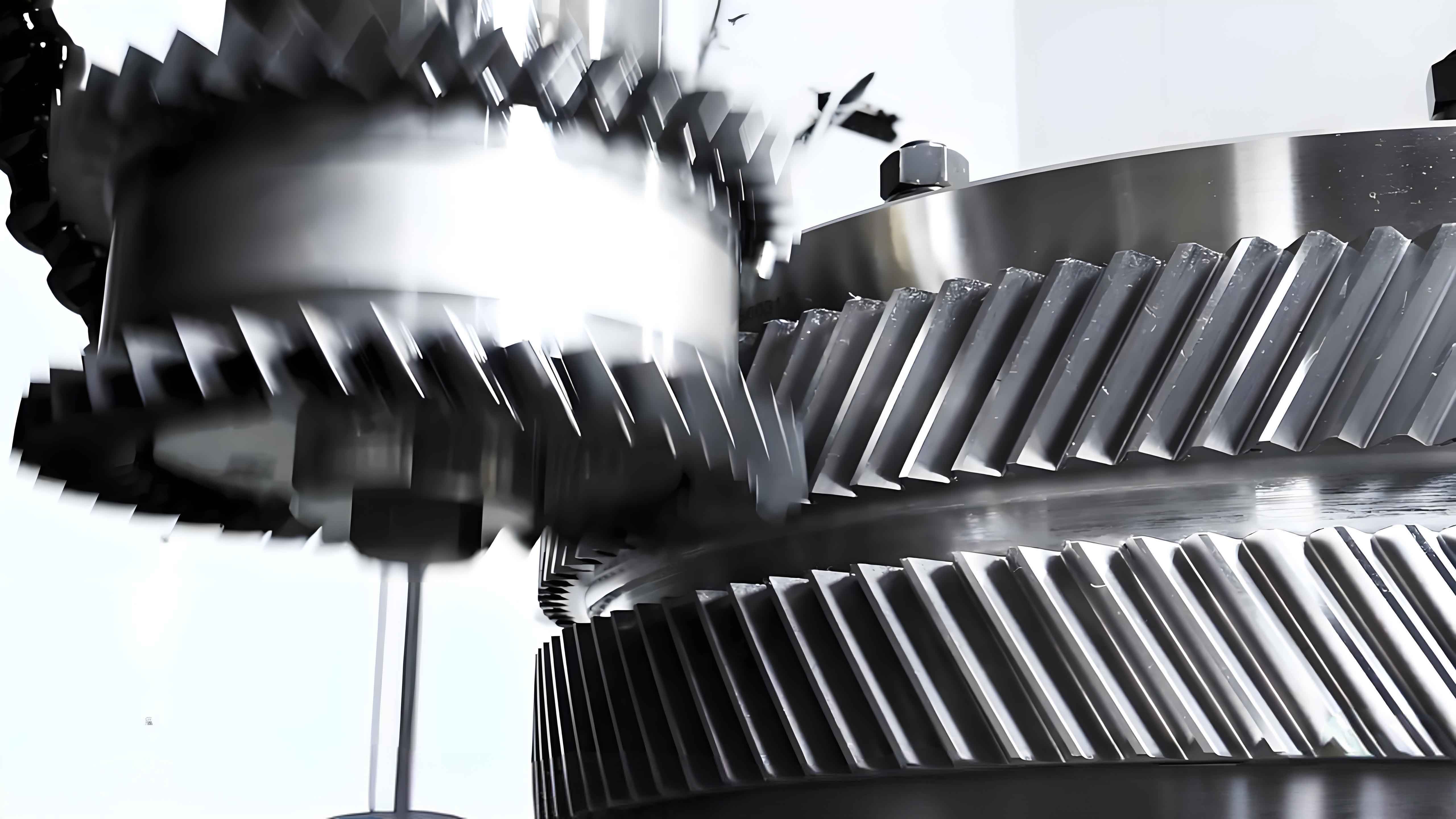
The core difficulty in machining a herringbone gear lies in the constraint imposed by the central clearance groove. Unlike a standard helical gear, the hobbing tool cannot perform a continuous axial feed from one end to the other. The narrow width of the groove means that as the finishing teeth of the hob complete one helix, the roughing teeth would already begin cutting into the opposing helix’s blank area, causing irreparable damage. Therefore, the process demands a non-standard, two-stage cutting strategy for each helix: a precise radial in-feed to full depth followed by an axial feed. The ultimate goal is to ensure the left-hand and right-hand helices converge exactly at the midpoint of the groove, with corresponding teeth aligned within a tight tolerance, often less than 0.20 mm for a Grade 7 gear. This symmetry, coupled with superior surface finish, is the definitive measure of success.
1. Foundational Theory and Machine Configuration
Successful machining begins with a flawless setup. The choice of machine is critical; a robust, precision hobbing machine with minimal play in its axes is essential. The mathematical setup involves calculating the correct change gears for indexing (dividing) and differential (to generate the helix).
1.1 Change Gear Calculations
For a hobbing machine with a fixed indexing constant (e.g., 48), the indexing change gear ratio for cutting a gear with tooth count \( Z \) is given by:
$$ \text{Indexing Ratio} = \frac{\text{Machine Constant}}{Z} = \frac{48}{Z} $$
This is implemented using a gear train \( \frac{a}{b} \times \frac{c}{d} \) to approximate this ratio.
The differential change gear ratio, which controls the rotary motion of the workpiece relative to the axial slide motion to generate the helix, is calculated using the helix angle \( \beta \) and the hob’s parameters:
$$ \text{Differential Ratio} = \frac{C \cdot \sin\beta}{K \cdot M_n} = \frac{a’ \times c’}{b’ \times d’} $$
Where:
\( C \) = Differential constant of the machine (e.g., 10)
\( \beta \) = Helix angle at the reference diameter
\( K \) = Number of starts on the hob (usually 1 for precision work)
\( M_n \) = Normal module of the herringbone gear
The hob swivel angle is set to \( \beta – \lambda \), where \( \lambda \) is the hob’s lead angle. For a single-start hob, \( \lambda \) is small.
| Parameter | Symbol | Example Value | Calculation / Note |
|---|---|---|---|
| Normal Module | \( M_n \) | 8.26194 mm | Defines tooth size in normal plane. |
| Number of Teeth | \( Z \) | 122 | Determines indexing ratio. |
| Helix Angle | \( \beta \) | 34° 17′ 25″ | Critical for differential calculation. |
| Indexing Ratio | – | 48/122 | Implemented as e.g., (48/60) × (30/61). |
| Differential Ratio | – | (10 sinβ) / \( M_n \) | Implemented as e.g., (40/45) × (56/73). |
| Hob Swivel Angle | – | \( \beta – \lambda \) ≈ 30° 39′ 25″ | Set on machine tool post. |
1.2 Workpiece and Tooling Setup
The fixture is the foundation of accuracy. Its locating face runout must be guaranteed to be within 0.02 mm. The fixture diameter should be slightly smaller than the gear root diameter to provide adequate support without interfering with the hob. When mounting the gear blank, extreme care must be taken to minimize radial and axial runout, as any error here directly translates into tooth spacing (accumulative pitch error) and tooth alignment (helix error) defects.
Tooling integrity is non-negotiable for herringbone gears where hobbing is often the final operation. The hob must be of premium quality, freshly sharpened, and mounted with fastidious care. The hob arbor must be straight and clean. The hob should be slid onto the arbor without force, ensuring full face contact on the mounting collars. When tightening the clamping nut, it is advisable to use a torque wrench to specified values to prevent arbor distortion, which would cause hob runout and poor tooth form.
2. The Two-Stage Cutting Strategy and Surface Finish Optimization
The machining of each helix of the herringbone gear follows a distinct sequence to overcome the groove constraint.
- Precise Radial In-feed: The hob is positioned at the start of the tooth space. Using manual radial feed, the hob is slowly and carefully fed into the workpiece until the full tooth depth is reached. This initial cut must be straight and aligned. Visual and auditory cues are important; the cut should be smooth and consistent.
- Axial Generation Feed: Once at full depth, the machine’s axial feed is engaged to generate the full length of the helix through the workpiece. The direction of feed (up or down) depends on the helix hand and machine configuration to ensure conventional milling.
Even with a correct strategy, surface defects like tearing, scoring, or chatter marks can occur. The mitigation strategy is multi-faceted:
- Machine Condition: The hydraulic system must be stable, with consistent pressure to avoid jerky table movements.
- Cutting Parameters: For finishing, use a conservative axial feed (e.g., 0.8-1.0 mm/rev of workpiece) and a moderate hob speed. A generous flow of high-quality cutting oil, directed at the cutting zone, is crucial for cooling, lubrication, and chip evacuation.
- Tool Management: This is the most critical factor. The common practice of using one hob for roughing and finishing until it is completely worn is disastrous for herringbone gear finish. The correct practice is to use a dedicated, freshly sharpened hob for the finishing pass on both helices. The roughing hob removes the bulk material, and a separate, sharp finishing hob takes the final cut. This ensures low cutting forces, minimal vibration, and a pristine surface finish free from the built-up edge and wear patterns of a tired tool.
| Process Stage | Hob Speed | Axial Feed | Radial Feed | Tool State | Coolant |
|---|---|---|---|---|---|
| Roughing | Medium-High | Moderate | Manual/Controlled | Sharp, but can be dedicated to roughing | High Volume |
| Finishing | Medium (40-60 rpm) | Fine (0.8-1.2 mm/rev) | Already at full depth | Freshly Sharpened / Dedicated Finishing Hob | High Volume & Pressure |
3. The Art of Symmetry: Marking and Alignment Techniques
After machining the first helix (e.g., left-hand), the workpiece must be prepared for machining the opposing helix with perfect symmetry. This is the heart of herringbone gear machining. The goal is to create a visual reference on the unmachined side that mirrors the finished side relative to the groove center.
3.1 Principle and Custom Marking Fixture
The reference is not the groove center itself, which is difficult to measure from, but the two newly machived tooth flanks near the groove. A custom “Π-shaped” fixture is used. It consists of two parallel reference blocks connected by a bridge, with fine-adjustment screws. The steps are as follows:
- Surface Preparation: A small area on the machined tooth tip land near the groove is lightly cleaned with a stone to provide a smooth, flat reference surface. The corresponding area on the blank side is coated with layout fluid (e.g., Prussian blue).
- Fixture Setup: The Π-fixture is placed over the groove. The two reference blocks are gently adjusted via their screws until they contact the cleaned reference surfaces on the machined flank. They are then locked in place. This fixture now embodies the spatial relationship of the machined flank.
- Transferring the Line: The entire fixture is carefully lifted and transferred to the blank side, ensuring it is oriented the same way. A scribe or height gauge is then run along the edge of the reference blocks to scribe two parallel lines on the layout fluid of the blank. These lines are projections of the machined flank’s position.
- Creating Datum Points: Using a square, vertical lines are scribed from these parallel lines at the desired start position for the new tooth space. The intersection points, especially the innermost ones closest to the gear body, become the primary visual datums for setting the hob.
This method minimizes error propagation by using the actual machined geometry as a direct reference, avoiding cumulative errors from measuring the groove width or center.
3.2 Achieving Symmetry in the Cut
With the workpiece marked and repositioned for cutting the second helix, the differential gears must remain identical to those used for the first helix to guarantee the same helix angle. After performing a roughing cut on the second side, the symmetry is evaluated by comparing the developing tooth form to the scribed lines.
Precise final alignment is achieved through one of two micro-adjustment techniques:
Method A: Indexing Micro-Adjustment. After the rough cut, the machine is stopped at a safe position. The indexing change gear is disengaged. By manually rotating this gear by a single tooth and re-engaging it, the workpiece rotates by a tiny, controlled amount \( \Delta \theta \):
$$ \Delta \theta \approx \frac{360^\circ}{Z \cdot N} $$
where \( N \) is the ratio of the change gear train. This angular shift translates to a minute lateral shift of the tooth space, allowing for precise alignment of the hob with the scribed marks.
Method B: Hob Axial Phase Adjustment. A dial indicator is mounted on the machine column with its tip touching the hob’s shank or a reference collar. After the rough cut, the hob’s axial phase (its rotational position about its own axis) is adjusted slightly by loosening the hob and rotating it a minuscule amount before re-tightening. The dial indicator reads this change. A more practical in-cut variation involves using the machine’s tool slide tangential adjustment. A wrench is used to gently “tap” the tool slide adjuster while the cut is very light, then slightly backed off to compensate for system backlash. This directly shifts the hob’s cutting edges relative to the workpiece.
Both methods are used iteratively during light finishing cuts until the cut aligns perfectly with the scribed datum lines, ensuring the left and right flanks are symmetric about the groove center.
| Error Source | Effect on Herringbone Gear | Prevention / Compensation Technique |
|---|---|---|
| Fixture Runout | Tooth alignment error (Helix deviation) | Pre-fixture calibration < 0.02 mm runout. |
| Incorrect Differential Ratio | Mismatched helix angles, causing mis-meeting at groove. | Double-check calculation; use identical gear train for both sides. |
| Marking/Setup Inaccuracy | Lateral offset of one helix. | Use custom Π-fixture; reference innermost points. |
| Machine Backlash / Tool Deflection | Poor surface finish, inconsistent tooth form. | Use sharp tools, light finishing cuts, stabilize machine hydraulics. |
| Cumulative Indexing Error | Tooth-to-tooth spacing error on one side. | Ensure machine indexing mechanism is in good condition. |
4. Verification: A Simple yet Effective Symmetry Check
Post-machining inspection of symmetry is crucial. While coordinate measuring machines (CMM) offer the most data, a simple and effective workshop verification method can be implemented. Place the finished herringbone gear vertically on a surface plate, ensuring it is stable. Using a height gauge with a sharp probe, measure the vertical height of the tooth tip at the point where it intersects the gear’s inner face (the shoulder near the body) for a left-hand tooth. Then, measure the height of the corresponding right-hand tooth at the same relative location (same angular position, same axial position relative to the inner face). The difference \( \Delta H \) in these two height readings is a direct measure of the lateral symmetry error \( \Delta S \), where \( \Delta S \approx \Delta H \cdot \tan\beta \). For practical purposes, a simple comparison of \( \Delta H \) against the tolerance (e.g., 0.20 mm) is sufficient and highly reliable for process control.
$$ \Delta H = H_{LH} – H_{RH} $$
$$ \Delta S \approx \frac{\Delta H}{\tan\beta} $$
This method provides immediate, actionable feedback on the success of the alignment techniques used.
5. Conclusion and Process Philosophy
Manufacturing high-precision herringbone gears on conventional equipment is not merely a sequence of steps; it is a discipline of precision and process control. The methodology outlined—emphasizing rigorous machine setup, a two-stage cutting strategy, proactive tool management for surface finish, the use of a custom marking fixture for symmetry, and iterative micro-adjustment during finishing—forms a robust and repeatable process. The key insights are the non-negotiable requirement for a sharp finishing hob and the principle of using the machined geometry itself as the primary datum for the opposing flank. This approach transforms a challenging machining problem into a controlled, reliable operation. The techniques for symmetry adjustment and the simple height gauge verification method empower machinists to consistently produce herringbone gears where the left and right helices meet with precision, fully realizing the silent, powerful, and efficient performance that the herringbone gear design promises. As demands for higher power density and quieter operation grow, mastering these fundamental yet advanced techniques remains essential for any manufacturer of high-performance gear drives.