
In the development of modern agricultural machinery, the application of worm gears has become increasingly prevalent due to their unique advantages. These advantages include a compact structure, smooth and quiet operation, high single-stage transmission ratio, and self-locking capability. I have encountered these components in various agricultural applications, such as tractor steering gear systems, greenhouse rolling machine reducers, and handle adjustment mechanisms for walking tractors. However, the complex surface geometry of worm gears presents a significant challenge for three-dimensional modeling in SolidWorks. The traditional modeling process is often cumbersome and inefficient. To address this, I have developed a parametric design methodology that leverages the secondary development capabilities of SolidWorks, automating the modeling process and significantly improving design efficiency. This article details my approach to establishing a mathematical model, recording and editing macros, and finally developing a dedicated plugin for worm gears design.
The complexity of worm gears surfaces, especially the convoluted helicoidal surfaces of the worm and the involute profiles of the worm wheel, makes standard manual modeling in SolidWorks a time-consuming and error-prone task. I realized that by establishing a precise mathematical foundation, I could programmatically control the generation of these complex geometries. The core of my methodology involves using Visual Basic to interact with SolidWorks’ Application Programming Interface (API). By recording a macro of the manual modeling process, I could capture the necessary API commands. I then edited this macro to replace fixed dimensions with variables, creating a parametric model. Finally, I developed a user-friendly plugin that allows engineers to input basic parameters and automatically generate the complete three-dimensional solid model. This approach not only simplifies the design workflow but also lays a strong foundation for subsequent finite element analysis and kinematic simulations within the agricultural machinery design cycle.
Mathematical Foundation for Worm Gears Modeling
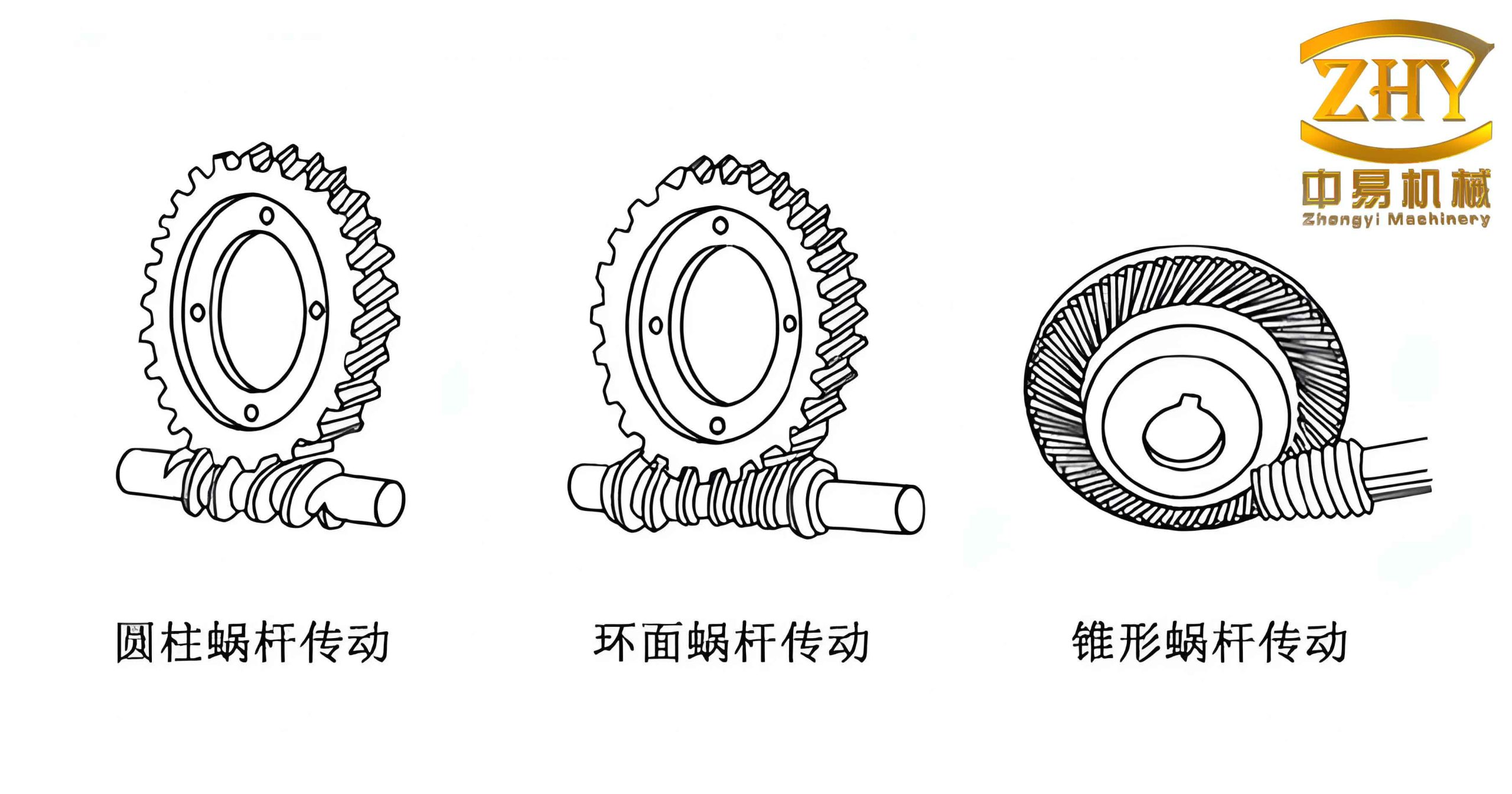
I began my work by focusing on the most common type, the Archimedean cylindrical worm. The fundamental principle of worm gears meshing is often analyzed in the central plane, which is the plane passing through the worm’s axis and perpendicular to the worm wheel’s axis. In this central plane, the worm meshes with the worm wheel as a rack and pinion, where the worm’s tooth profile is a straight-sided rack, and the worm wheel’s tooth profile is an involute curve. For the worm itself, a cross-section perpendicular to its axis reveals an Archimedean spiral (or involute spiral for other types). The modeling of the worm is achieved by creating a tooth profile and then performing a cut-sweep along a helical path.
I established the mathematical model for the worm’s tooth profile as shown in the coordinate system below. The profile is a trapezoid that, when swept along the helix, forms the worm thread. The coordinates of the vertices of this trapezoid are:
$$
\begin{aligned}
\vec{X}_1 &= \left( \frac{p_x}{4} + \tan\alpha \frac{d_{a1} – d_1}{2}, \frac{d_{a1}}{2} \right) \\
\vec{Y}_1 &= \left( \frac{p_x}{4} – \tan\alpha \frac{d_1 – d_{f1}}{2}, \frac{d_{f1}}{2} \right) \\
\vec{X}_2 &= \left( -\frac{p_x}{4} + \tan\alpha \frac{d_1 – d_{f1}}{2}, \frac{d_{f1}}{2} \right) \\
\vec{X}_3 &= \left( -\frac{p_x}{4} – \tan\alpha \frac{d_{a1} – d_1}{2}, \frac{d_{a1}}{2} \right)
\end{aligned}
$$
where:
- \( \alpha \) is the pressure angle (typically 20°).
- \( d_{a1} \) is the addendum circle diameter of the worm.
- \( d_1 \) is the pitch circle diameter of the worm.
- \( d_{f1} \) is the dedendum circle diameter of the worm.
- \( p_x \) is the axial pitch of the worm.
- \( z_1 \) is the number of starts (threads) of the worm.
The modeling steps I followed for the worm were:
- Base Solid Creation: I created a cylindrical base body by extruding a circle with a diameter equal to the addendum circle diameter \( d_{a1} \). The extrusion length was set to the worm length \( L \).
- Helix Creation: I generated an Archimedean helix. The base circle diameter of this helix is the worm’s pitch circle diameter \( d_1 \). The height of the helix is the worm length \( L \), and the pitch is the lead of the worm \( p_z = z_1 \cdot p_x \).
- Tooth Profile Creation: I created a sketch of the tooth profile on a plane tangent to the cylinder. The profile was a trapezoid defined by the vertices calculated above.
- Swept Cut: I performed a swept cut using the tooth profile as the profile and the helix as the path. This creates a single thread.
- Circular Pattern (for Multi-start worm gears): For multi-start worms, I applied a circular pattern feature around the worm’s central axis. The number of instances equals the number of starts \( z_1 \).
For the worm wheel, the mathematical model is more complex because its teeth have an involute profile in the central plane. Since SolidWorks does not have a built-in function to draw an involute curve directly, I computed the coordinates of points on the involute using its parametric equations and then connected these points with a spline curve to approximate the involute. The involute of a circle is defined by the following parametric equations:
$$
\begin{aligned}
X(r_k) &= r_k \sin(\phi + \theta_k) \\
Y(r_k) &= r_k \cos(\phi + \theta_k) \\
\theta_k &= \tan\alpha_k – \alpha_k \\
\alpha_k &= \arccos\left(\frac{r_b}{r_k}\right) \\
\phi &= \frac{\pi}{2z_2} – \tan\alpha + \alpha
\end{aligned}
$$
Here, \( d_2 \) is the pitch circle diameter of the worm wheel, and \( r_k \) varies between \( d_{f2}/2 \) and \( d_{a2}/2 \) (the radii of the dedendum and addendum circles of the worm wheel). The value \( z_2 \) is the number of teeth on the worm wheel. The modeling procedure I developed for the worm wheel was as follows:
- Blank Creation: I created a cylindrical blank representing the worm wheel’s outer diameter.
- Tooth Space Profile Creation: Using the parametric equations, I generated a set of points for one flank of an involute. I mirrored this flank to create the other side, thus forming a tooth space. The tooth space is bounded by the two involute flanks, the addendum circle (root circle on the blank), and the dedendum circle (tip circle on the wheel).
- Swept Cut for Tooth Space: I used this tooth space profile and swept it along a helical path (defined on a new reference plane) to perform a cut.
- Circular Pattern: I arrayed this “cut-sweep” feature around the worm wheel’s central axis to create all the teeth.
- Finishing Features: Finally, I added standard features such as chamfers, fillets, and keyway slots to complete the model.
Parametric Design Process
The core of my work was to automate the tedious process described above. I achieved this through SolidWorks’ powerful secondary development capabilities. My primary tool was the “Macro” feature. A macro records user actions (mouse clicks, menu selections, keyboard input) and translates them into a VB (Visual Basic) script. This is a very efficient way to learn the necessary API functions without having to look them up in the documentation. The workflow I established is a cycle of “Record -> Edit -> Compile -> Package”.
Recording the Macro
I started by opening a new SolidWorks part. I then went to Tools > Macro > Record. I proceeded to manually model a worm and a worm wheel using the steps outlined earlier. All the modeling commands, such as extruding, creating helices, drawing lines, performing sweeps, and circular patterns, were recorded. After finishing the model, I stopped the macro recorder and saved it. This generated a *.swp file containing the VB code for the entire modeling process. This code was very verbose, containing many redundant selections and view changes.
Editing the Macro for Parametrization
The most critical step was editing the recorded macro. I opened the macro in the Visual Basic Editor (available within SolidWorks). My editing goals were to:
- Declare Variables: I declared variables for all the design parameters, such as module \( m \), number of worm starts \( z_1 \), number of worm wheel teeth \( z_2 \), pressure angle \( \alpha \), and center distance \( a \). From these fundamental parameters, I could calculate derived parameters.
- Remove Redundancy: I removed all code related to view changes (e.g., zooming, rotating), temporary graphics, and repeated selections that were not essential for the model’s geometry.
- Modify API Function Parameters: I replaced the hard-coded numerical values in the API function calls with my declared variables. For example, instead of FeatureManager.FeatureExtrusion2(True, False, False, 0, 0, 0.1, 0.01, …), I would use a variable like length for the extrusion depth.
- Key Logic for Multi-start worm gears: A critical part of the code was the circular pattern. The key API call is Part.FeatureManager.FeatureCircularPattern2. I modified this to use the number of worm starts \( z_1 \) and the angular pitch \( 2\pi / z_1 \). The code snippet for this is:
boolstatus = Part.Extension.SelectByID2("Cut-Sweep1", "BODYFEATURE", 0, 0, 0, False, 4, Nothing, 0)
boolstatus = Part.Extension.SelectByID2("", "AXIS", 0, 0, 0, True, 1, Nothing, 0)
Part.FeatureManager.FeatureCircularPattern2(z1, 2*PI / z1, False, "NULL", False)
I also added a user interface (UI) to the macro. I created a Windows Form in the VB Editor. This form contained input fields (textboxes) for the user to enter the basic parameters of the worm gears. I programmed the “Generate” button to read the values from these textboxes, assign them to the variables, and then run the core modeling code. This created a complete, interactive macro application.
Creating a SolidWorks Plugin (Add-In)
To provide a more professional and integrated user experience, I decided to compile the macro into a full-fledged SolidWorks Add-In. The steps I took were:
- Environment Setup: I installed Microsoft Visual Studio and the SolidWorks API SDK (Software Development Kit).
- Project Creation: I created a new project using the “SolidWorks Add-In” template in Visual Basic.NET.
- Importing the Macro Code: I imported the core modeling code from my edited macro into the Add-In project.
- Adding References: I added references to the SolidWorks type library (e.g., SolidWorks.Interop.sldworks) and the constant type library (SolidWorks.Interop.swconst). This allows the code to access SolidWorks objects and their predefined constants.
- Building the UI: I recreated the user interface (the form with input fields) within the Visual Studio designer.
- Compiling: I compiled the project. This generated a *.dll file, which is the SolidWorks Add-In.
The table below summarizes the key differences between the traditional macro and the compiled Add-In for this parametric design task.
| Feature | Macro (.swp) | Add-In (.dll) |
|---|---|---|
| Deployment | Simple, just a file | Requires installation/registration |
| Integration | Runs in macro editor | Seamless integration with SolidWorks UI, can add custom menus/toolbars |
| Performance | Slower, interpreted | Faster, compiled code |
| Stability | More prone to errors from user interruptions | More stable, can handle errors gracefully |
| User Experience | Popup window, less integrated | Custom toolbar buttons, dockable panels |
Loading and Using the Plugin
Once the Add-In was compiled, I needed to load it into SolidWorks. I navigated to Tools > Add-Ins. In the dialog, I located my *.dll file and selected it. The plugin then appeared in the list of available add-ins. I could check the box to load it at startup. To make it more convenient, I also created a custom toolbar. Figure 2 shows the plugin’s toolbar icon, which I placed on a newly created toolbar group. Engineers can now click this icon to launch my parametric design interface for worm gears.
Advantages and Further Development
The parametric design system I developed offers several significant advantages for engineers working with worm gears:
- Dramatically Reduced Modeling Time: What once took 30-60 minutes can now be accomplished in under a minute.
- Elimination of Modeling Errors: The process is automated, removing the risk of manual errors in complex operations like sweep cuts and patterns.
- Standardized Design Process: All models are created using the same underlying math, ensuring consistency across different designs.
- Foundation for Further Analysis: The 3D models are parametric, making it easy to perform “what-if” scenarios by changing the basic parameters and regenerating the model for finite element analysis or motion studies.
- Integration with Drawings: The 3D model is bidirectional with 2D drawings. Once the model is generated, I can automatically create engineering drawings with accurate dimensions, tolerances, and a bill of materials. I have pre-configured drawing templates in Excel that automatically populate these details.
In conclusion, my work on the parametric design of worm gears based on SolidWorks provides a powerful and efficient tool for the design of modern agricultural machinery. By combining a strong mathematical foundation with the robust API of SolidWorks, I have transformed a complex and tedious manual task into a simple, automated process. The resulting plugin allows for rapid generation of accurate 3D models, directly from the fundamental parameters of worm gears. This innovation not only saves valuable design time but also enhances the overall quality and reliability of the design, setting a strong precedent for the parametric design of other complex mechanical components in the agricultural sector. The ability to quickly iterate on the design of worm gears is crucial for optimizing the performance and durability of agricultural machines like tractors, harvesters, and greenhouse equipment.