
In my work on mechanical assembly drawings, I have found that parametric drawing is one of the most practical ways to reduce repetitive effort and improve consistency. AutoLISP is an artificial-intelligence-oriented language embedded directly inside AutoCAD, and it gives me a direct way to call AutoCAD drawing commands and internal functions. By writing small applications in AutoLISP, I can generate standard mechanical components quickly, especially screw gears such as worm and worm-wheel transmissions. In an assembly drawing, screw gears appear frequently because they transmit motion and power between two intersecting shafts, often with a large reduction ratio and a compact layout. My goal is to show how I use AutoLISP to parameterize the main view and the left-section view of screw gears so that a user can obtain different screw gear configurations by entering only a few values.
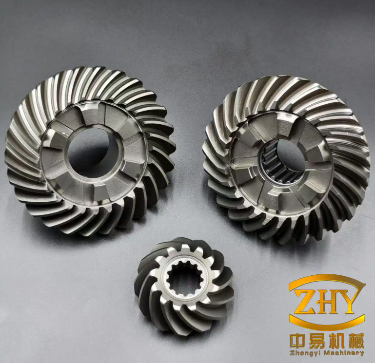
Standard components do not change very much in shape. Once a set of parameters is given, the complete geometry of screw gears can be determined. Manual drafting of screw gears takes a long time, is prone to mistakes, and consumes design time that should be spent on structural decisions. Parametric drawing replaces that repetitive work with a controlled mathematical model. The user supplies the required values, and the program calculates all remaining dimensions and inserts the geometry. In my AutoLISP implementation, the user can generate different types of screw gears in a few seconds, and the resulting geometry can be edited further inside the assembly drawing. This approach is especially useful for screw gears because their tooth form, hub, keyway, and section views follow well-defined relationships.
The common parameters of screw gears include the module, pressure angle, diameter coefficient, lead angle, number of worm starts, number of worm-wheel teeth, addendum coefficient, and clearance coefficient. The module and pressure angle are standard values on the axial plane of the worm and on the end plane of the worm wheel. The diameter coefficient is the ratio of the worm reference diameter to its module. In my parameterization, I treat the module, the number of worm starts, the number of worm-wheel teeth, the diameter coefficient, the overall rotation angle, and the center location as primary inputs. Additional inputs include the worm-wheel shaft-hole diameter, keyway width, and keyway hub depth. These values are sufficient to construct a complete two-view representation of screw gears for assembly drawings.
$$d = m q$$
$$h_a = m$$
$$h_f = 1.2m$$
$$d_a = m(q + 2)$$
$$L = 16m \quad \text{for } z_1 = 1,2$$
$$L = 20m \quad \text{for } z_1 = 3,4$$
$$a = m(q + z_2)$$
$$d_2 = m z_2$$
$$B = 0.75(d + 2h_a) \quad \text{for } z_1 = 2,3,4$$
$$B = 0.67(d + 2h_a) \quad \text{otherwise}$$
In the equations above, \(d\) is the worm reference diameter, \(m\) is the module, \(q\) is the diameter coefficient, \(h_a\) is the addendum, \(h_f\) is the dedendum, \(d_a\) is the worm tip diameter, \(L\) is the threaded length of the worm, \(z_1\) is the number of worm starts, \(z_2\) is the number of worm-wheel teeth, \(a\) is the center distance in my simplified parametric model, \(d_2\) is the worm-wheel reference diameter, and \(B\) is the worm-wheel width. These relationships allow me to compute every point needed for the drawing of screw gears without asking the user for secondary dimensions.
The following table summarizes the main parameters that I use when I parameterize screw gears in an assembly drawing. I keep these values in a dialog-driven data structure so that the drawing functions can retrieve them directly.
| Symbol | Meaning in Screw Gears | Typical Value or Relationship |
|---|---|---|
| \(m\) | Module | Standard value, \(m > 0\) |
| \(\alpha\) | Pressure angle | Usually 20 degrees |
| \(q\) | Diameter coefficient | \(q = d / m\) |
| \(\gamma\) | Lead angle | \(\tan\gamma = z_1 / q\) |
| \(z_1\) | Number of worm starts | 1, 2, 3, or 4 |
| \(z_2\) | Number of worm-wheel teeth | Integer, usually large |
| \(h_a^*\) | Addendum coefficient | 1 |
| \(c^*\) | Clearance coefficient | 0.2 |
| \(d\) | Worm reference diameter | \(d = m q\) |
| \(d_a\) | Worm tip diameter | \(d_a = m(q + 2)\) |
| \(d_2\) | Worm-wheel reference diameter | \(d_2 = m z_2\) |
| \(L\) | Threaded length of worm | \(16m\) or \(20m\) |
| \(B\) | Worm-wheel width | \(0.75(d + 2h_a)\) or \(0.67(d + 2h_a)\) |
| \(a\) | Center distance | \(a = m(q + z_2)\) in the simplified model |
When I write the AutoLISP program, I divide it into several cooperating parts. The first part is the dialog box, which collects the parameters from the user. The second part is the mathematical model, which converts the input values into all dimensions and point coordinates needed for screw gears. The third part is the annotation section, which prepares text and dimension placement. The fourth part is the drawing environment section, which manages layers, object snap, and other system variables. The fifth part is the drawing section, which calls AutoCAD commands to create the geometry. The sixth part is the menu section, which allows the user to choose among several types of screw gears. This structure keeps the program readable and makes it easy to extend to other standard components.
In my parametric drawing workflow, the user first selects the type of screw gears from a menu. The program then loads the corresponding AutoLISP file and displays a dialog box. The dialog box contains edit boxes for the module, number of worm starts, number of worm-wheel teeth, diameter coefficient, overall rotation angle, worm-wheel shaft-hole diameter, keyway width, keyway hub depth, and the center location. The center location is the center point of the worm. Different assembly drawings may require different insertion points, so I allow the user to either type the X and Y coordinates or pick a point on the screen. After the user confirms the values, the program computes the remaining dimensions, builds the screw gear geometry, and outputs the main view and the left-section view. The user can then move or edit the generated screw gears as needed.
The drawing environment in an assembly drawing is usually already established. Therefore, my program should not permanently change the original environment settings. When I switch layers, I first check whether the layer exists. If the layer does not exist, I switch to the default layer instead. For example, when I want to use a layer named for thick continuous lines, I use a conditional test. The logic is expressed in AutoLISP as follows:
(if (tblobjname “layer” “thick_line”)
(command “clayer” “thick_line”)
(command “clayer” “0”))
For other drawing environment settings, such as object snap, I save the original value at the beginning of the program and restore it at the end. This is important because the user may have specific snap settings for the assembly drawing. The AutoLISP statements follow this pattern:
(setq osmode_bak (getvar “osmode”))
(setvar “osmode” 0)
… drawing operations …
(setvar “osmode” osmode_bak)
This practice makes the parametric drawing of screw gears safe inside an existing assembly drawing. I do not want the generation of screw gears to disturb the user’s current layer, snap, or selection settings. By restoring the environment, I keep the assembly drawing stable and predictable.
The dialog box is written in DCL, the dialog control language that accompanies AutoLISP. DCL uses a tree-like structure with rows and columns. A row arranges controls horizontally, and a column arranges them vertically. Common controls include buttons, edit boxes, image buttons, list boxes, drop-down lists, radio buttons, sliders, and toggle switches. For screw gears, I mainly use edit boxes and command buttons. Each edit box has a label that tells the user which parameter to enter, and a key that links the control to the AutoLISP driver. The driver reads the key values, assigns them to variables, and passes them to the mathematical model.
The following table lists the controls that I use in the dialog for screw gears and the role of each control.
| Control Type | Purpose in Screw Gear Dialog | Key or Action |
|---|---|---|
| Edit box | Enter module | M_box |
| Edit box | Enter number of worm starts | Z1_box |
| Edit box | Enter number of worm-wheel teeth | Z2_box |
| Edit box | Enter diameter coefficient | Q_box |
| Edit box | Enter overall rotation angle | ALF_box |
| Edit box | Enter worm-wheel shaft-hole diameter | dm_box |
| Edit box | Enter keyway width | B1_box |
| Edit box | Enter keyway hub depth | T1_box |
| Edit box | Enter X coordinate of center point | X_box |
| Edit box | Enter Y coordinate of center point | Y_box |
| Button | Pick center point on screen | pick |
| Button | Confirm all values | accept |
| Button | Cancel the dialog | cancel |
In my DCL file, the dialog is organized as a vertical column. The first group of edit boxes collects the geometric parameters of screw gears. The second group collects the hub and keyway parameters. The third group collects the center location. A button allows the user to pick the center point directly from the drawing. The OK and Cancel buttons are provided by the standard DCL clause. A simplified version of the DCL structure is shown below:
ptwg:dialog {
label = “Screw gear parameters”;
alignment = centered;
: column {
: edit_box { label = “Rotation angle ALF (rad):”; key = “ALF_box”; width = 12; }
: edit_box { label = “Number of worm starts Z1:”; key = “Z1_box”; width = 12; }
: edit_box { label = “Number of worm-wheel teeth Z2:”; key = “Z2_box”; width = 12; }
: edit_box { label = “Axial module M:”; key = “M_box”; width = 12; }
: edit_box { label = “Diameter coefficient Q:”; key = “Q_box”; width = 12; }
: edit_box { label = “Worm-wheel shaft-hole diameter dm:”; key = “dm_box”; width = 12; }
: edit_box { label = “Keyway width B1:”; key = “B1_box”; width = 12; }
: edit_box { label = “Keyway hub depth T1:”; key = “T1_box”; width = 12; }
: boxed_column {
label = “Center point”;
: edit_box { label = “X coordinate:”; key = “X_box”; width = 12; }
: edit_box { label = “Y coordinate:”; key = “Y_box”; width = 12; }
: button { label = “Pick on screen <“; key = “pick”; }
}
}
ok_cancel;
}
The main program contains the dialog loading function, the initialization function, the control action functions, the parameter assignment function, the control state functions, the main calling function, the drawing functions for each view, and other supporting statements. When I load the DCL file, I use the AutoLISP function load_dialog. If the dialog cannot be loaded, the program exits. Then I call new_dialog to initialize the dialog. If the dialog cannot be initialized, the program exits. After that, I set initial values for the controls with set_tile. For example, I often set the number of worm starts to 2 as a default value for screw gears.
(setq id (load_dialog “E:\\screw_gears\\test.DCL”))
(if (< id 0) (exit))
(if (not (new_dialog “ptwg” id)) (exit))
(setq z1 2)
(set_tile “Z1_box” (rtos z1 2 2))
I use action_tile to define what happens when the user presses a button or changes a value. For the accept button, I call a function that reads all the data and then closes the dialog. The pattern is:
(action_tile “accept” “(getdata) (done_dialog 1)”)
To read a value from an edit box, I use get_tile and convert the string to a real number when necessary. For the number of worm starts, the statement is:
(setq z1 (atof (get_tile “Z1_box”)))
This technique is repeated for every parameter of screw gears. Once all values are extracted, the mathematical model is called. The model computes the remaining dimensions and stores them in variables. Then the drawing functions use those variables to create the geometry.
The mathematical model is the core of the parametric drawing of screw gears. The user supplies the module, the number of worm starts, the number of worm-wheel teeth, the diameter coefficient, the overall rotation angle, the center point, the worm-wheel shaft-hole diameter, the keyway width, and the keyway hub depth. From these values, I compute the worm dimensions and the worm-wheel dimensions. The worm dimensions include the reference diameter, addendum, dedendum, tip diameter, root diameter, and threaded length. The worm-wheel dimensions include the reference diameter, tip diameter, root diameter, width, and center distance. I also compute the keyway geometry and the section profile.
The following table lists the worm dimensions that I compute for screw gears. These values are used directly in the main view and the left-section view.
| Dimension | Formula | Description |
|---|---|---|
| Reference diameter \(d\) | \(d = m q\) | Pitch diameter of the worm |
| Addendum \(h_a\) | \(h_a = m\) | Height above the reference line |
| Dedendum \(h_f\) | \(h_f = 1.2m\) | Depth below the reference line |
| Tip diameter \(d_a\) | \(d_a = m(q + 2)\) | Outside diameter of the worm |
| Root diameter \(d_f\) | \(d_f = d – 2h_f = m(q – 2.4)\) | Root diameter of the worm |
| Threaded length \(L\) | \(L = 16m\) for \(z_1 = 1,2\) | Length of the threaded portion |
| Threaded length \(L\) | \(L = 20m\) for \(z_1 = 3,4\) | Length of the threaded portion |
The worm-wheel dimensions are computed in a similar way. The reference diameter is \(d_2 = m z_2\). The tip diameter is \(d_{a2} = d_2 + 2h_a\). The root diameter is \(d_{f2} = d_2 – 2h_f\). The width \(B\) depends on the number of worm starts. For \(z_1 = 2,3,4\), I use \(B = 0.75(d + 2h_a)\). For other values, I use \(B = 0.67(d + 2h_a)\). The center distance in my simplified model is \(a = m(q + z_2)\). These formulas give me the complete outline of the worm wheel, including the throat profile and the hub.
The keyway is another important detail in screw gears, especially when the worm wheel is mounted on a shaft. I compute the keyway width \(B_1\) and the keyway hub depth \(T_1\) from the user input. The keyway is drawn in the left-section view. The hub diameter and the shaft-hole diameter determine the local geometry around the keyway. By including these details in the parametric program, I make the generated screw gears more useful in a real assembly drawing, where the shaft and key are often shown in section.
To compute point locations, I use the AutoLISP polar function. The polar function returns a point based on a known point, an angle, and a distance. For example, if I know point \(p_2\), I can find point \(p_4\) by specifying an angle of \(1.5\pi\) radians and a distance of \(d + 2h_a\). The statement is:
(setq p4 (polar p2 (* 1.5 pi) (+ d (* ha 2))))
This function is very convenient for screw gears because many features are located at specific angles and distances from the center. I use polar repeatedly to build the main view, the section view, the hub, the keyway, and the tooth profiles. By combining polar with basic AutoCAD commands, I can construct the entire geometry without hard-coding every coordinate.
The drawing functions call standard AutoCAD commands. I use command to switch layers, draw lines, draw circles, trim edges, and hatch sections. For example, to switch the current layer to a thick continuous line layer, I use:
(command “clayer” “thick_line”)
To draw a line between two points, I use:
(command “line” p5 p6 “”)
To draw a circle with a known center and diameter, I use:
(command “circle” pt0 “d” d1)
To trim a circle or a line, I use the trim command with selected cutting edges and objects to trim. The statement is:
(command “trim” pt6 “” pt5 pt4 “”)
To hatch a section, I use the bhatch command. The following example fills a region with the ANSI31 pattern at a scale of 0.5 and an angle of 0:
(command “bhatch” “p” “ansi31” 0.5 0 pm1 pm2 “” “”)
These commands are sufficient for the main view and the left-section view of screw gears. The main view shows the worm, the worm wheel, the shaft center lines, and the center distance. The left-section view shows the worm-wheel hub, the shaft hole, the keyway, and the tooth profile in section. Together, these two views give a complete representation of screw gears for an assembly drawing.
The following table summarizes the drawing functions that I use most often in the parametric drawing of screw gears.
| Function or Command | Purpose | Example |
|---|---|---|
| polar | Compute a point from distance and angle | (setq p4 (polar p2 (* 1.5 pi) (+ d (* ha 2)))) |
| command “clayer” | Switch the current layer | (command “clayer” “thick_line”) |
| command “line” | Draw a line segment | (command “line” p5 p6 “”) |
| command “circle” | Draw a circle | (command “circle” pt0 “d” d1) |
| command “trim” | Trim unwanted geometry | (command “trim” pt6 “” pt5 pt4 “”) |
| command “bhatch” | Hatch a section area | (command “bhatch” “p” “ansi31” 0.5 0 pm1 pm2 “” “”) |
| getvar | Read a system variable | (getvar “osmode”) |
| setvar | Set a system variable | (setvar “osmode” 0) |
After the drawing functions finish, the program restores the original environment. The object snap value is set back to its saved value. The layer is left as the user had it, unless the user chooses to keep the generated screw gears on a new layer. This restoration step is important because an assembly drawing often contains many existing entities, and the parametric drawing of screw gears should not interfere with them. The user can then adjust line types, line weights, and dimensions according to the drawing standard.
To make the program easy to use, I create a custom menu. The menu contains several types of screw gears. Through the menu, the user can choose a standard worm, a standard worm wheel, a toroidal worm, a toroidal worm wheel, a double-enveloping worm, or a double-enveloping worm wheel. Each menu item loads the corresponding AutoLISP file and calls the main drawing function. The menu can be implemented as a CUI file. After saving the CUI file and the associated MNR file, the user loads it with the cuiload command. The user enters cuiload at the command line, selects the CUI file, clicks Load, and then clicks Close. After that, the screw gear commands are available from the menu.
The following table lists the menu items that I include for screw gears and the function of each item.
| Menu Item | Function | Typical Use |
|---|---|---|
| Standard worm | Draw a standard cylindrical worm | Main view of screw gears |
| Standard worm wheel | Draw a standard worm wheel | Main view and section view of screw gears |
| Toroidal worm | Draw a toroidal worm | Special screw gears with curved profile |
| Toroidal worm wheel | Draw a toroidal worm wheel | Special screw gears with curved profile |
| Double-enveloping worm | Draw a double-enveloping worm | High-load screw gears |
| Double-enveloping worm wheel | Draw a double-enveloping worm wheel | High-load screw gears |
When I run the program with suitable parameters, I obtain a two-view representation of screw gears. The main view shows the worm and the worm wheel in engagement. The left-section view shows the worm-wheel hub, the shaft hole, the keyway, and the sectioned teeth. The geometry changes automatically when the user changes the module, the number of worm starts, the number of worm-wheel teeth, or the diameter coefficient. This means that a single AutoLISP program can generate many different screw gears without redrawing the entire assembly. The user can insert the generated screw gears into an existing assembly drawing, move them to the correct position, and continue with the rest of the design.
In my experience, the parametric drawing of screw gears has several advantages. First, the program is readable and easy to modify. AutoLISP is simple enough that a designer with limited programming experience can understand the logic and change the formulas. Second, the dialog box makes the program easy to operate. The user does not need to remember many command names or parameter orders. The dialog box shows each parameter with a label, and the user fills in the values. Third, the program reduces errors. Because the geometry is computed from formulas, the same input always produces the same output. This consistency is valuable for screw gears, where a small error in the tooth profile or center distance can cause interference in the assembly. Fourth, the program saves time. Manual drafting of screw gears can take hours, while the parametric program takes only seconds. Fifth, the program can be extended. I can add more types of screw gears, more section details, or more annotation functions without rewriting the entire application.
The mathematical model can be further summarized in a compact form. For screw gears, the worm reference diameter is proportional to the module and the diameter coefficient. The addendum and dedendum are proportional to the module. The threaded length depends on the number of worm starts. The worm-wheel reference diameter depends on the module and the number of teeth. The center distance depends on the module, the diameter coefficient, and the number of worm-wheel teeth. These relationships are shown below.
$$d = m q$$
$$d_a = m(q + 2)$$
$$d_f = m(q – 2.4)$$
$$d_2 = m z_2$$
$$d_{a2} = m(z_2 + 2)$$
$$d_{f2} = m(z_2 – 2.4)$$
$$a = m(q + z_2)$$
$$L = \begin{cases} 16m, & z_1 = 1,2 \\ 20m, & z_1 = 3,4 \end{cases}$$
$$B = \begin{cases} 0.75(d + 2h_a), & z_1 = 2,3,4 \\ 0.67(d + 2h_a), & \text{otherwise} \end{cases}$$
These formulas are the basis of my parametric drawing. When the user enters the primary parameters, the program evaluates these expressions and stores the results. The drawing functions then use the results to place lines, circles, arcs, and hatches. Because the formulas are explicit, the program can also check for invalid inputs. For example, if the module is zero or negative, the program can display a warning and ask the user to enter a positive value. If the number of worm starts is not an integer, the program can round it or reject it. These checks improve the reliability of the generated screw gears.
I also pay attention to the order of operations. The program first loads the dialog, then reads the parameters, then computes the dimensions, then sets the drawing environment, then draws the geometry, and finally restores the environment. This order prevents the drawing environment from being changed before the user has confirmed the parameters. It also ensures that the mathematical model has all the values it needs before the drawing functions are called. In an assembly drawing, this order is especially important because the user may cancel the dialog. If the user cancels, the program should exit without changing the drawing. I implement this by checking the return value of the dialog and exiting if the user cancels.
The left-section view of screw gears requires special attention. The section shows the worm-wheel hub, the shaft hole, the keyway, and the teeth. The hub is usually a cylinder with a keyway cut into it. The shaft hole is a circle with a diameter given by the user. The keyway is a rectangular cut with width \(B_1\) and depth \(T_1\). The teeth are shown in section with hatching. To draw this view, I compute the hub outer diameter, the hub length, the keyway position, and the tooth profile. I then draw the outline, trim the intersections, and hatch the cut material. The hatching pattern and scale can be adjusted by the user. In my program, I use the ANSI31 pattern with a scale of 0.5 as a default, but the user can change it after the geometry is generated.
The main view of screw gears shows the worm and the worm wheel in engagement. The worm appears as a cylinder with a threaded section. The worm wheel appears as a circle with a throat. The center distance between the worm axis and the worm-wheel axis is \(a\). The worm is usually drawn with its axis horizontal, and the worm wheel is drawn with its axis vertical. The program draws the center lines, the reference circles, the tip circles, the root circles, and the tooth profile. In the engagement region, the program trims the overlapping lines and shows the contact. This view is important because it shows the relative position and the overall size of the screw gears in the assembly.
The following table summarizes the two views that I generate for screw gears and the main entities in each view.
| View | Main Entities | Purpose in Assembly Drawing |
|---|---|---|
| Main view | Worm outline, worm-wheel outline, center lines, reference circles, tip circles, root circles, engagement region | Show the relative position and overall size of screw gears |
| Left-section view | Worm-wheel hub, shaft hole, keyway, sectioned teeth, hatching | Show the internal structure and mounting details of screw gears |
I have found that the use of tables and formulas greatly improves the maintainability of the AutoLISP program. When a formula changes, I only need to update one place in the code. When a new parameter is added, I add a row to the dialog and a corresponding formula to the mathematical model. This modular approach is suitable for screw gears because their design is standardized. The module, pressure angle, diameter coefficient, and addendum coefficient are standard values. The number of worm starts and the number of worm-wheel teeth are design choices. The keyway dimensions depend on the shaft diameter. By separating these categories, I can make the program flexible and robust.
Another benefit of parametric drawing is that the generated screw gears can be used as a starting point for further design. The user can modify the geometry after it is created. For example, the user can change the hub length, add fillets, or adjust the keyway. The parametric program does not lock the geometry. It simply creates the base geometry quickly and accurately. This is important in assembly drawings because the designer often needs to fit the screw gears with other components. The ability to edit the generated screw gears saves time and reduces frustration.
In my implementation, I also provide a screen pick option for the center point. The user can click a button in the dialog and then pick a point in the drawing. The program returns the coordinates of the picked point and fills the X and Y edit boxes. This feature is convenient because the user does not need to measure coordinates manually. The program then uses the picked point as the worm center. The worm-wheel center is computed from the center distance. In the main view, the worm-wheel center is placed at a distance \(a\) from the worm center. In the left-section view, the worm-wheel center is placed at the same location, and the section is drawn around it.
The center distance \(a\) is one of the most important parameters in screw gears. If the center distance is incorrect, the worm and the worm wheel will not mesh properly. In my simplified model, I use \(a = m(q + z_2)\). In a more precise model, the center distance would be \(a = \frac{m(q + z_2)}{2}\). I note this difference because the parametric drawing can be adapted to either convention. The user can choose the convention that matches the design standard. The important point is that the center distance is computed from the primary parameters, not entered separately. This reduces the chance of inconsistency between the worm and the worm-wheel positions.
The lead angle \(\gamma\) is another important parameter. It is related to the number of worm starts and the diameter coefficient by:
$$\tan\gamma = \frac{z_1}{q}$$
The lead angle affects the efficiency and the self-locking behavior of screw gears. In my dialog, I do not ask the user to enter the lead angle directly. Instead, I compute it from \(z_1\) and \(q\). I can display the computed lead angle in the drawing or in a message for the user. This helps the designer verify that the screw gears meet the required performance. If the lead angle is too small, the screw gears may be self-locking. If the lead angle is too large, the efficiency may be higher but the design may be more difficult to manufacture. By computing the lead angle automatically, I make the parametric drawing more informative.
The following table summarizes the computed values that I display or use in the parametric drawing of screw gears.
| Computed Value | Formula | Use in Drawing |
|---|---|---|
| Lead angle \(\gamma\) | \(\tan\gamma = z_1 / q\) | Check efficiency and self-locking |
| Worm tip diameter \(d_a\) | \(d_a = m(q + 2)\) | Draw outer circle of worm |
| Worm root diameter \(d_f\) | \(d_f = m(q – 2.4)\) | Draw root circle of worm |
| Worm-wheel tip diameter \(d_{a2}\) | \(d_{a2} = m(z_2 + 2)\) | Draw outer circle of worm wheel |
| Worm-wheel root diameter \(d_{f2}\) | \(d_{f2} = m(z_2 – 2.4)\) | Draw root circle of worm wheel |
| Center distance \(a\) | \(a = m(q + z_2)\) | Locate worm-wheel center |
| Threaded length \(L\) | \(16m\) or \(20m\) | Draw threaded section of worm |
| Worm-wheel width \(B\) | \(0.75(d + 2h_a)\) or \(0.67(d + 2h_a)\) | Draw width of worm wheel |
I also use the program to draw the keyway in the left-section view. The keyway width \(B_1\) and the keyway hub depth \(T_1\) are entered by the user. The keyway is positioned at the top of the shaft hole. The program draws two vertical lines and one horizontal line to form the keyway. It then trims the shaft-hole circle to create the opening. This detail is important for screw gears because the worm wheel is usually mounted on a shaft with a key. The assembly drawing must show the keyway clearly. By including this detail in the parametric program, I make the generated screw gears ready for assembly documentation.
The annotation section of the program is also parameterized. The program can place dimensions for the center distance, the worm diameter, the worm-wheel diameter, and the keyway. The user can choose whether to display these dimensions. In an assembly drawing, dimensions are often omitted or shown only on detail drawings. Therefore, I make annotation optional. The program can also place text for the module, the number of teeth, and the lead angle. This information helps the reader understand the screw gears without referring to a separate table. The annotation is placed on a separate layer so that the user can turn it on or off easily.
The drawing environment section includes layer management, object snap management, and other system variables. I check for the existence of layers before switching to them. If a layer does not exist, I use the default layer. I save the object snap value and set it to zero during drawing. After drawing, I restore the object snap value. I also save the current layer and restore it if necessary. These steps ensure that the parametric drawing of screw gears does not disrupt the assembly drawing. The user can continue working with the existing layers and settings without any unexpected changes.
The menu section makes the program accessible to users who do not want to type AutoLISP commands. The menu contains a hierarchy of screw gear types. The user selects the desired type, and the program loads the corresponding LISP file. The dialog box then appears, and the user enters the parameters. After the geometry is generated, the user can repeat the process for other screw gears. The menu can be loaded with the cuiload command. The user can also create a toolbar or a ribbon panel if desired. The important point is that the parametric drawing of screw gears is integrated into the AutoCAD interface in a way that is familiar and convenient.
In conclusion, I have described a practical method for the parametric drawing of screw gears in assembly drawings using AutoLISP. The method uses a dialog box to collect parameters, a mathematical model to compute dimensions, and a set of drawing functions to create the main view and the left-section view. The program handles layers, object snap, and other environment settings carefully so that it can be used inside an existing assembly drawing. The user can generate many different screw gears by entering the module, the number of worm starts, the number of worm-wheel teeth, the diameter coefficient, and other parameters. The resulting geometry is accurate, consistent, and easy to edit. I believe that this approach can be extended to other standard mechanical components and can significantly improve the efficiency of assembly drawing production. The repeated use of screw gears in mechanical systems makes this kind of parametric tool especially valuable, and the combination of AutoLISP, DCL, and AutoCAD commands provides a reliable foundation for further development.