
The accurate modeling of gear is an important basis for analyzing the contact stress and crack propagation law of gear. A pair of low-speed and heavy gears are taken as the research object, and the gear type is spur gear.
Gear parametric modeling is completed by using the equation tab and equation driving curve in SolidWorks, and its process is slightly complicated. In the SolidWorks tool tab, open the equation, input the heavy gear parameter under the global variable, input the gear parameter letter on the left, and input the specific value on the right.

Create a new sketch and select spline curve, add equation driving curve, input involute equation to get involute curve. The root circle, base circle, index circle and addendum circle are created by using the equation, as shown in Figure 1. Draw a horizontal construction line, and cut the dividing circle, leaving an arc intersecting with the construction line and involute, and then define the dividing circle with the equation; Create an arc and tangent to the tooth root circle and involute respectively, define the arc radius with equation, and draw the result as shown in Figure 2.

Stretch the sketch, stretch the length of 710 mm, get a tooth, and then array the other teeth, as shown in Figure 3.

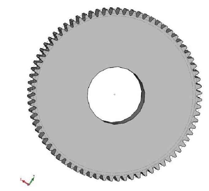
A 840 mm diameter hole is cut in the center of the heavy gear, and the final three-dimensional model of the heavy gear is shown in Figure 4. The modeling method of the pinion is the same as that of the heavy gear, and a 400 mm diameter hole is cut in the center of the pinion. The three-dimensional model of the pinion is shown in Figure 5.

Assemble the heavy gear and the small gear. The assembly type is the gear fit in the mechanical fit. The three-dimensional model of the assembly is shown in Figure 6.
