
Worm gear drives are widely utilized in machinery due to their compact structure, large transmission ratio, smooth operation, and reliable self‑locking capability under certain conditions. They appear in machine tools, automobiles, instruments, hoisting machinery, metallurgical equipment, and many other devices. However, the complex tooth profile of worm gears makes it difficult to directly create three‑dimensional solid models using conventional CAD/CAM software. I have experienced that UGNX, originally developed by EDS (now Siemens PLM Software), provides a powerful integrated platform for CAD/CAE/CAM with strong parametric design capabilities. By combining parametric modeling with feature‑based design, UGNX allows dimension‑driven or variable‑driven definition of features. In particular, its tools such as “law curve,” “expression,” and “dynamic WCS” enable the construction of intricate tooth curves. Nevertheless, for engineers unfamiliar with the software, the learning curve is steep. In this paper, I present a systematic approach to parametric modeling of an Archimedean worm gear pair using UGNX, which can serve as a reference for modeling other complex solids.
Geometric Characteristics of Worm Gear Drives
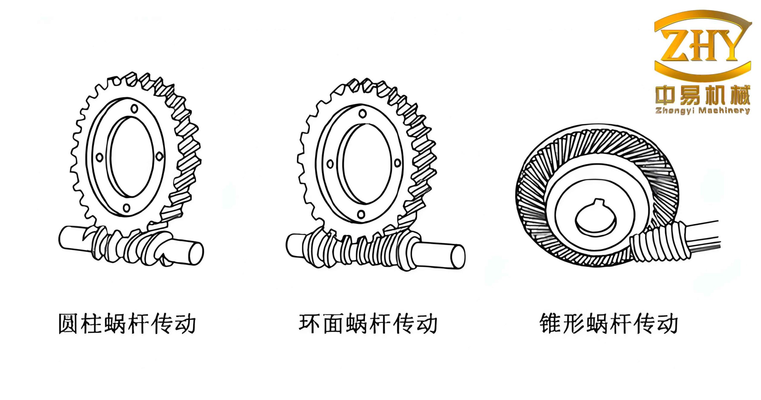
A worm gear pair evolved from crossed‑axis helical gears. The worm resembles a screw with threads winding more than one full turn around the pitch cylinder. To improve meshing, the worm wheel’s pitch cylinder is replaced by a circular arc so that the wheel partially envelops the worm. The worm is usually manufactured with a hob having identical shape and parameters, achieving line contact between teeth and enabling transmission of higher power. The geometric structure of the worm is shaft‑like, consisting of different cylindrical sections with features such as teeth, keyways, chamfers, and undercuts. The worm wheel is a disk‑like part whose main body is a revolute with teeth, holes, ribs, and keyways.
Parametric Modeling of the Worm
I created an Archimedean worm with the following parameters: axial module ma = 2 mm, number of worm threads z1 = 1, pressure angle α = 20°, lead angle γ = 4°23’55”, pitch circle diameter = 26 mm, addendum circle diameter = 30 mm, and dedendum circle diameter = 21 mm. The modeling process consisted of several steps.
1. Establishing the Worm Blank
The worm blank is a revolute body. Using the sketch tool in UGNX, I drew a 2D cross‑section as shown in the initial design (Figure 1 of the original work). All dimensions in the sketch are parametric; modifying them later automatically updates the solid model. The solid blank was then created by the “Revolve” operation. A chamfer was added to the edges. The resulting base is a simple stepped cylinder.
2. Creating the Tooth Space Profile
I used the “Dynamic WCS” function to rotate the working coordinate system (ZC axis) by the lead angle γ, ensuring that the sketch plane for the tooth space is perpendicular to the worm helix. The tooth space profile (Figure 3 in the original) includes key dimensions: the angle A = 70° (derived from the pressure angle), the radial offset B = addendum radius + 0.1 mm (to facilitate Boolean subtraction), and the radial depth C = dedendum radius. This profile forms the cutting tool shape.
3. Generating the Helix Curve
A helix was created using the “Insert → Curve → Helix” command. The radius was set to the worm pitch circle radius (13 mm). The pitch was calculated to match the desired lead. The generated helix serves as the guide curve for the subsequent sweep operation.
4. Creating the Helical Swept Body
With the “Swept” command, I used the helix as the guide and the tooth space profile as the cross‑section to create a solid helix body. This body represents the material to be removed from the worm blank.
5. Subtracting to Form Teeth
Using the Boolean “Subtract” operation, I selected the worm blank as the target and the swept helix as the tool. After subtraction, the teeth appeared. Finally, I added edge blends on the tooth tips and a keyway feature at the shaft end. The completed worm model is illustrated.
The following table summarizes the key parameters used for the worm:
| Parameter | Symbol | Value |
|---|---|---|
| Axial module | ma | 2 mm |
| Number of threads | z1 | 1 |
| Pressure angle | α | 20° |
| Lead angle | γ | 4°23’55” |
| Pitch circle diameter | dp | 26 mm |
| Addendum circle diameter | da | 30 mm |
| Dedendum circle diameter | df | 21 mm |
Parametric Modeling of the Worm Wheel (Gear)
The worm wheel parameters were: normal module mn = 2 mm, number of teeth z2 = 27, pressure angle α = 20°, lead angle γ = 4°23’55”, pitch circle diameter = 54 mm, addendum circle diameter = 62 mm, dedendum circle diameter = 49 mm, face width = 25 mm, throat diameter = 58 mm, and center distance = 40 mm. The modeling steps are described below.
1. Creating the Worm Wheel Blank
First, I created a cylinder for the wheel body using the “Cylinder” command. Then I added a central bore using “Extrude” and “Boolean Subtract”. A spherical groove was cut on the outer surface of the wheel to accommodate the worm; the groove radius equals the center distance minus the throat radius (11 mm), and the groove diameter equals the pitch circle diameter (54 mm). The blank now resembles a cylindrical disk with a concave waist.
2. Generating the Involute Tooth Profile
The tooth profile of the worm wheel is an involute. The involute curve can be described by parametric equations in Cartesian coordinates based on the generation of a straight line rolling on a base circle. The equations are:
$$ x = r_b \cos \varepsilon + r_b \varepsilon \sin \varepsilon $$
$$ y = r_b \sin \varepsilon – r_b \varepsilon \cos \varepsilon $$
where rb is the base radius and ε is the rolling angle. In UGNX, I used the “Law Curve → By Equation” method. First, I defined the following expressions under “Tools → Expressions”:
| Expression Name | Formula | Description |
|---|---|---|
| m | 2 | Normal module (mm) |
| z | 27 | Number of teeth |
| angle | 20 | Pressure angle (degrees) |
| rb | m * z * cos(angle) / 2 | Base circle radius (mm) |
| t | 0.001 | Increment parameter for curve points |
| s | t * 45 | Rolling angle (degrees) |
| xt | rb * cos(s) + rb * rad(s) * sin(s) | X‑coordinate |
| yt | rb * sin(s) – rb * rad(s) * cos(s) | Y‑coordinate |
| zt | 0 | Z‑coordinate (planar) |
Using these expressions, the law curve generated a precise involute lying in the XY plane.
3. Constructing the Tooth Space Tool Body
Next, I sketched three concentric circles representing the addendum, pitch, and dedendum circles. The involute curve was extracted into the sketch using the “Offset Curve” command and then blended with the dedendum circle via a fillet to produce one side of a tooth space. A line from the center to the intersection of the involute and the pitch circle was drawn. Another line was created at an angle of (360/27/4) degrees from the first one to define the tooth space symmetry. One line was set as a reference (mirror line). The “Mirror Curve” command created the other side of the tooth space, producing a closed profile for one tooth slot. After trimming, I obtained the final cross‑section.
To align with the worm helix, I rotated the entire sketch by –4°23’55” about the XC axis. Then I created a helix curve (with a pitch matching the worm) to serve as a guide. Using the “Swept” command, I swept the rotated tooth space profile along the helix, generating a solid tool body representing the material to be removed for one tooth gap.
4. Generating All Teeth on the Worm Wheel
I used the “Edit → Transform” command with “Copy” and “Rotate” to reproduce the tool body 26 times around the wheel axis, with a rotation increment of 360°/27 = 13.333°. The 27 copies (including the original) cover all tooth spaces. Finally, a “Boolean Subtract” operation was performed, selecting the worm wheel blank as the target and all 27 tool bodies as the cutting tools. The result is a fully toothed worm wheel solid model.
The following table summarizes the key parameters of the worm wheel:
| Parameter | Symbol | Value |
|---|---|---|
| Normal module | mn | 2 mm |
| Number of teeth | z2 | 27 |
| Pressure angle | α | 20° |
| Lead angle | γ | 4°23’55” |
| Pitch circle diameter | dp | 54 mm |
| Addendum circle diameter | da | 62 mm |
| Dedendum circle diameter | df | 49 mm |
| Face width | b | 25 mm |
| Throat diameter | dt | 58 mm |
| Center distance | a | 40 mm |
Assembly and Simulation
After obtaining both solid models, I assembled the worm and worm wheel in the UGNX assembly environment by applying proper mating conditions (e.g., parallel axes at a defined center distance). The assembled pair can be visualized. The software’s interference check and dynamic collision detection can then be performed, and the motion of the worm gear drive can be animated. The following figure shows the typical appearance of a worm gear set.
Conclusion
I have demonstrated a complete parametric modeling process for an Archimedean worm gear drive using UGNX. The method fully leverages the hybrid modeling capabilities of the software, combining feature‑based parametric modeling with sketch‑driven dimensions. The use of expressions, law curves, and dynamic WCS allows accurate construction of complex tooth profiles. The generated solid models can serve as the foundation for subsequent engineering analyses such as finite element analysis, motion simulation, interference checking, and surface quality evaluation. This approach is not limited to worm gears; it can be adapted to other complex geometric shapes requiring parametric flexibility.
The key advantages of this parametric approach include easy modification of design parameters (e.g., module, number of teeth, lead angle) by simply updating the corresponding expressions or sketches, which automatically regenerates the entire model. This greatly accelerates the design iteration process and reduces manual rework. Moreover, the methodology enables designers to perform virtual prototyping, thus shortening the product development cycle and improving design reliability.
In summary, the parametric modeling of worm gear drives in UGNX provides a powerful and efficient workflow. The results presented here can assist engineers in mastering the techniques required for modeling other complex solids, ultimately enhancing the overall CAD/CAM capability in mechanical design.