This article focuses on the parametric precision modeling of bevel gears using MATLAB and Creo Parametric software. Bevel gears, especially spiral bevel gears, are crucial in mechanical engineering. However, their complex structure and numerous parameters pose challenges to modeling. By leveraging the power of MATLAB for parameter calculation and Creo Parametric for 3D modeling, a systematic approach is presented. This approach simplifies the modeling process, enhances efficiency, and provides a practical solution for engineers and researchers in the field. Through detailed steps, including parameter definition, gear blank modeling, and tooth profile creation, the entire modeling workflow is elucidated. Additionally, the integration of 3D printing technology for physical prototype production is discussed, highlighting its significance in rapid prototyping and product development.
1. Introduction
1.1 Importance of Bevel Gears
Bevel gears play a vital role in mechanical transmission systems. They are used to transmit power and motion between intersecting shafts, making them essential in various applications such as automotive differentials, industrial machinery, and aerospace components. Spiral bevel gears, in particular, offer advantages like smoother operation, higher load – carrying capacity, and quieter performance compared to straight bevel gears due to their unique tooth arrangement.
1.2 Challenges in Bevel Gear Modeling
Modeling bevel gears, especially spiral bevel gears, is a complex task. The numerous parameters involved, such as pitch cone angle, face width, module, and helix angle, require precise calculation and understanding. Traditional manual modeling methods are time – consuming and error – prone. Moreover, the complex tooth profile, especially in spiral bevel gears, makes it difficult to create an accurate model using simple geometric operations.
1.3 Objectives of This Study
The main objectives of this study are to develop a parametric precision modeling method for bevel gears. This involves using MATLAB to calculate gear parameters accurately and Creo Parametric to create 3D models. The method aims to simplify the modeling process, reduce errors, and enable quick modification of gear models by changing basic parameters. Additionally, the integration of 3D printing technology will be explored to produce physical prototypes for verification and testing.
2. Literature Review
Many researchers have focused on bevel gear modeling. Some studies use different 3D modeling software like SolidWorks, CATIA, and UG. For example, [1] established the involute equation in MATLAB and imported discrete points into SolidWorks for arc – tooth bevel gear modeling. [2] studied parametric modeling of spiral bevel gears based on CATIA and optimized some gear parameters. However, most of these studies lack detailed descriptions of the modeling process, making it difficult for engineers to follow and apply in practical work.
3. Parameter Calculation of Bevel Gears
3.1 Definition of Basic Parameters
Before starting the modeling process, it is essential to define the basic parameters of bevel gears. These parameters include the module (m), number of teeth (z), pressure angle (α), pitch cone angle (δ), and face width (b). Table 1 summarizes these basic parameters and their significance in bevel gear design.
| Parameter | Symbol | Significance |
|---|---|---|
| Module | m | Determines the size of the gear teeth and is related to the gear’s load – carrying capacity. A larger module generally indicates larger teeth and higher load – carrying capacity. |
| Number of Teeth | z | Affects the gear ratio and the overall size of the gear. The gear ratio is determined by the ratio of the number of teeth of the driving and driven gears. |
| Pressure Angle | α | Influences the force transmission and the shape of the tooth profile. Common pressure angles are 20° or 25°. A larger pressure angle results in a stronger tooth root but may increase the sliding friction between teeth. |
| Pitch Cone Angle | δ | Defines the angle of the pitch cone, which is crucial for determining the orientation of the gear teeth and the meshing relationship between bevel gears. |
| Face Width | b | Affects the contact area and load – distribution along the tooth length. A wider face width can increase the load – carrying capacity but may also introduce more manufacturing challenges. |
| Table 1: Basic Parameters of Bevel Gears |
3.2 Calculation of Other Parameters
Based on the basic parameters, other important parameters such as the pitch diameter (d), addendum (ha), dedendum (hf), and outside diameter (da) can be calculated. The following formulas are used for the calculation:
- Pitch diameter: \(d = m\times z\)
- Addendum: \(h_a=m\times h_{ax}\) (where \(h_{ax}\) is the addendum coefficient, usually 1 for standard gears)
- Dedendum: \(h_f = m\times (h_{ax}+c_x)\) (where \(c_x\) is the clearance coefficient, typically 0.25 for standard gears)
- Outside diameter: \(d_a=d + 2\times h_a\times\cos\delta\)
Table 2 shows an example of parameter calculation results for a bevel gear with specific basic parameters.
| Parameter | Symbol | Calculation Result |
|---|---|---|
| Module | m | 4 |
| Number of Teeth | z | 25 |
| Pressure Angle | α | 20° |
| Pitch Cone Angle | δ | 30° |
| Face Width | b | 30 |
| Pitch Diameter | d | 100 |
| Addendum | h_a | 4 |
| Dedendum | h_f | 5 |
| Outside Diameter | d_a | 106.9282 |
| Table 2: Example of Bevel Gear Parameter Calculation Results |
3.3 Using MATLAB for Parameter Calculation
MATLAB can be used to automate the parameter calculation process. By writing a script in MATLAB, engineers can input the basic parameters and obtain all the necessary calculated parameters quickly and accurately. The following is a simple MATLAB code snippet for calculating bevel gear parameters.
4. Gear Blank Modeling in Creo Parametric
4.1 Setting Up the Workspace in Creo Parametric
Open Creo Parametric 9.0 software. Create a new part file and set the appropriate units, such as millimeters. Navigate to the “Model” tab, where most of the modeling operations will be performed.
4.2 Defining Parameters in Creo Parametric
In the “Model” tab, click on “Parameters” to open the parameter dialog box. Define all the parameters required for gear blank modeling, including the basic and calculated parameters from the previous section. Enter the known values for basic parameters and set the calculated parameters to 0 for now.
4.3 Creating the Gear Blank Sketch
Select a suitable plane, such as the TOP plane, to create a sketch. Use the sketching tools in Creo Parametric to draw the profile of the gear blank. For a bevel gear, the sketch typically includes a conical shape representing the pitch cone. Dimension the sketch using the defined parameters to ensure accuracy. Figure 1 shows an example of a bevel gear blank sketch.
4.4 Extruding the Gear Blank
After creating the sketch, use the “Extrusion” tool in the “Model” tab. Select the sketch and define the extrusion depth or distance. In the case of a bevel gear, the extrusion direction should be perpendicular to the sketch plane. Set the extrusion type to “Solid” to create a solid gear blank.
5. Modeling Straight Bevel Gears
5.1 Creating the Tooth Profile Sketch
To create the tooth profile of a straight bevel gear, first, calculate the tooth thickness at the pitch circle. The tooth thickness formula is \(s=\frac{\pi m}{2}\). Then, create a new sketch on a plane perpendicular to the pitch cone surface. Use the sketching tools to draw the tooth profile, which usually consists of straight lines for the sides of the tooth and arcs for the fillets. Dimension the sketch using the calculated tooth thickness and other relevant parameters.
5.2 Using the “Sweep” or “Extrusion” Feature for Tooth Creation
There are two common methods to create the teeth on the gear blank. One is to use the “Sweep” feature. Define a sweep path along the pitch cone surface and use the tooth profile sketch as the cross – section. Another method is to use the “Extrusion” feature. If using extrusion, create a sketch of the tooth profile on a plane parallel to the axis of the gear and extrude it to the appropriate depth. Figure 2 shows the tooth profile creation using the extrusion method.
5.3 Arraying the Teeth
Once a single tooth is created, use the “Pattern” or “Array” feature in Creo Parametric to create the remaining teeth. Set the array type to “Circular” and define the axis of rotation as the gear’s central axis. Specify the number of teeth and the angular increment between each tooth. For example, if the gear has 25 teeth, the angular increment is \(\frac{360^{\circ}}{25}=14.4^{\circ}\). After arraying, a complete straight bevel gear model is obtained.
6. Modeling Spiral Bevel Gears
6.1 Understanding the Spiral Tooth Geometry
Spiral bevel gears have a more complex tooth geometry compared to straight bevel gears. The teeth are arranged in a spiral shape, which requires a different approach for modeling. The spiral angle (\(\beta\)) is an important parameter that determines the shape and orientation of the spiral teeth.
6.2 Creating the Spiral Tooth Path
To create the spiral tooth path, first, define a reference plane. In Creo Parametric, create a new plane that is perpendicular to the axis of the gear and intersects the pitch cone. On this plane, draw a spiral curve. The equation for a spiral curve can be defined using polar coordinates. For example, \(r = r_0 + k\theta\), where \(r_0\) is the initial radius, k is a constant that determines the pitch of the spiral, and \(\theta\) is the angular coordinate. Figure 3 shows a spiral curve drawn on a reference plane.
6.3 Sketching and Sweeping the Tooth Profile along the Spiral Path
Similar to straight bevel gear modeling, create a tooth profile sketch. Then, use the “Sweep” feature in Creo Parametric. Select the tooth profile sketch as the cross – section and the spiral curve as the sweep path. This will create a single spiral tooth on the gear blank.
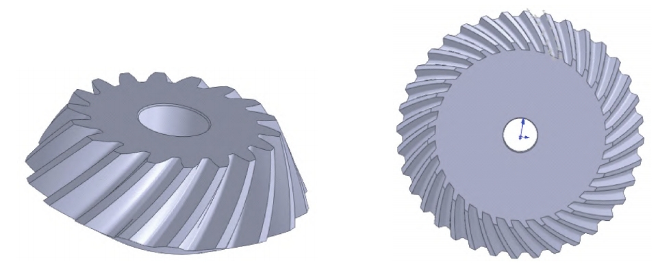
6.4 Arraying and Finalizing the Spiral Bevel Gear Model
After creating a single spiral tooth, use the “Pattern” or “Array” feature to create the remaining teeth. The process is similar to that of straight bevel gears, but with the added complexity of the spiral tooth orientation. Once all the teeth are created, check the model for any errors or inconsistencies. Make necessary adjustments to the tooth profile, spiral path, or other parameters to ensure the accuracy of the model.
7. 3D Printing of Bevel Gears
7.1 Preparing the Model for 3D Printing
Before 3D printing, the bevel gear model in Creo Parametric needs to be exported in a suitable format, such as STL (Stereolithography). In the “File” menu, select “Save As” and choose the STL format. Set the appropriate tolerance and resolution for the STL file to ensure accurate representation of the model.
7.2 Slicing the Model
Import the STL file into a slicing software, such as Cura or PrusaSlicer. The slicing software will divide the 3D model into layers and generate a G – code file that can be read by the 3D printer. In the slicing software, set parameters such as layer height, wall thickness, infill density, and printing speed. Table 3 shows an example of 3D printing parameter settings for bevel gears.
| Parameter | Value |
|---|---|
| Layer Height | 0.2 mm |
| Wall Thickness | 1.2 mm |
| Infill Density | 10% |
| Printing Speed | 40 mm/s |
| Nozzle Temperature | 210 °C |
| Bed Temperature | 40 °C |
| Support Type | Local Support |
| Platform Adhesion Type | Bottom Edge |
| Printing Material | PLA |
| Material Diameter | 1.75 mm |
| Extrusion Amount | 100% |
| Nozzle Diameter | 0.4 mm |
| Retraction Speed | 40 mm/s |
| Retraction Length | 4 mm |
| Initial Layer Height | 0.2 mm |
| Initial Layer Line Width | 100% |
| Bottom Layer Not Removed | Yes |
| Extrusion Overlap | 0.15 mm |
| Moving Speed | 40 mm/s |
| Bottom Layer Printing Speed | 40 mm/s |
| Infill Printing Speed | 40 mm/s |
| Top and Bottom Layer Printing Speed | 40 mm/s |
| Outer Wall Printing Speed | 40 mm/s |
| Inner Wall Printing Speed | 40 mm/s |
| Minimum Cooling Time per Layer | 5 s |
| Fan Cooling | On |
| Table 3: 3D Printing Parameter Settings for Bevel Gears |
7.3 3D Printing Process and Post – Processing
Load the G – code file into the 3D printer and start the printing process. During the printing process, monitor the printer to ensure proper operation. After printing, remove the bevel gear from the build plate and perform post – processing steps. Post – processing may include removing support structures, sanding the surface to improve smoothness, and painting the gear if necessary. Figure 4 shows a 3D – printed spiral bevel gear.
8. Verification and Validation of the Model
8.1 Comparing the 3D – Printed Model with the Theoretical Model
Measure the dimensions of the 3D – printed bevel gear using measuring tools such as calipers or coordinate measuring machines (CMMs). Compare the measured dimensions with the theoretical dimensions calculated during the modeling process. Calculate the errors between the measured and theoretical values and analyze the sources of errors.
8.2 Testing the Functionality of the Bevel Gear
Assemble the 3D – printed bevel gear into a test rig to test its functionality. Check for smooth meshing, proper rotation, and absence of abnormal noises or vibrations. If any issues are found, analyze the reasons and make improvements to the modeling process.
9. Applications and Future Trends
9.1 Applications of Bevel Gears
Bevel gears are widely used in various industries. In the automotive industry, they are used in differentials to distribute power between the left and right wheels. In industrial machinery, bevel gears are used in conveyor systems, gearboxes, and machine tools. In aerospace applications, bevel gears are used in aircraft engines and landing gear systems.
9.2 Future Trends in Bevel Gear Modeling
With the development of technology, future trends in bevel gear modeling include the use of more advanced simulation techniques. Finite element analysis (FEA) can be integrated into the modeling process to analyze the stress distribution, deformation, and fatigue life of bevel gears. Additionally, the use of artificial intelligence and machine learning algorithms may be explored to optimize gear design parameters and improve the efficiency of the modeling process.
10. Conclusion
This article presents a comprehensive guide to the parametric precision modeling of bevel gears using MATLAB and Creo Parametric. By calculating parameters in MATLAB and creating 3D models in Creo Parametric, a systematic approach for bevel gear modeling is established. The integration of 3D printing technology enables the rapid production of physical prototypes for verification and testing. The parametric modeling method simplifies the process, reduces errors, and allows for quick modification of gear models. Future research can focus on further improving the modeling accuracy, integrating more advanced simulation techniques, and exploring the use of new materials for bevel gear manufacturing.