
I carried out an integrated study of a locomotive pinion gear shaft that showed abnormal growth of its bearing seats during maintenance. The pinion gear is one of the most highly loaded rotating components in a locomotive drive system. It transmits motor torque to the driven gear, and its bearing seats must maintain a precise interference fit with bearing inner rings. When the bearing seat diameter grows by even a few hundredths of a millimeter, the effective interference, contact pressure, inner-ring stress, and operating clearance can all move outside acceptable limits. My objective was therefore twofold: first, to identify the root cause of the abnormal bearing seat growth, and second, to establish a repeatable procedure for deciding whether a used pinion gear shaft can be returned to service.
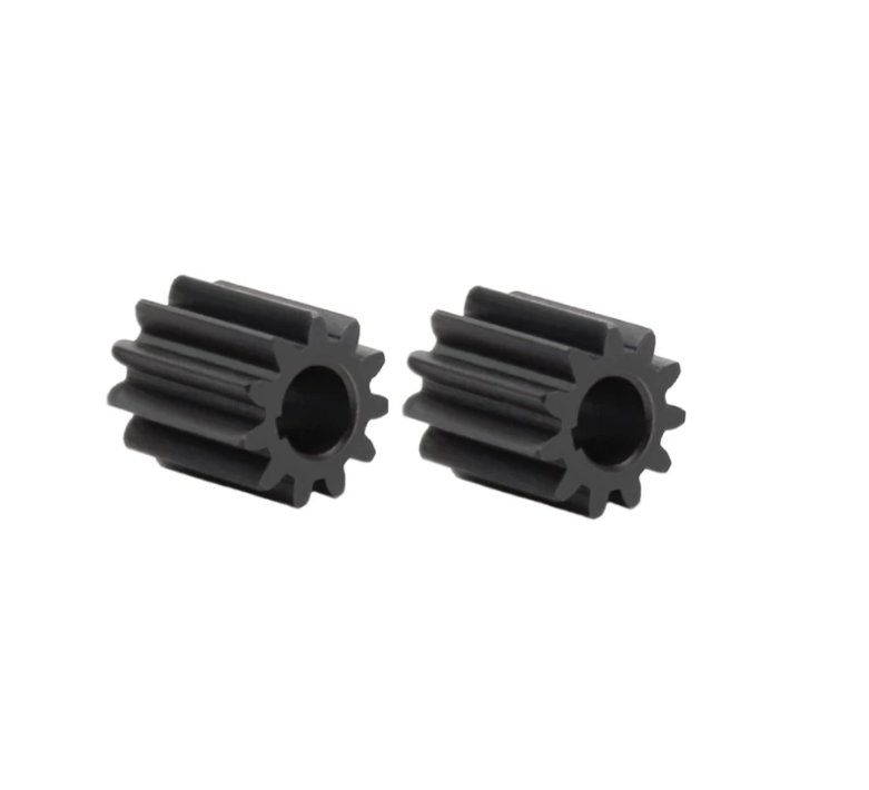
I treated the pinion gear shaft as a coupled thermal, metallurgical, and mechanical system. The manufacturing route includes heat treatment, and the service route includes repeated mechanical loading and thermal cycling. In the maintenance inspection, the pinion gear shaft bearing seats were found to be larger than the original acceptance range. The measured growth was between approximately 0.01 mm and 0.12 mm, and both domestic and imported pinion gear shafts exhibited the same phenomenon. Because the pinion gear must operate with several bearing types, including cylindrical roller bearings and a four-point contact ball bearing, any increase in seat diameter changes the interference state of every bearing inner ring mounted on the pinion gear.
Engineering consequence. If the interference is too large, the bearing inner ring expands excessively. The expansion reduces the internal radial clearance, distorts the raceway geometry, increases contact stress, and may eventually cause ring cracking or premature fatigue. For a locomotive pinion gear, such a failure can interrupt traction power and create a serious safety risk. Therefore, I linked the dimensional anomaly to both the heat-treatment history and the final interference fit.
Heat-treatment simulation. I first simulated the actual heat-treatment cycle of the pinion gear. The material was 17Cr2Ni2Mo low-carbon alloy steel, and the nominal chemical composition is summarized in the following table.
| Element | C | Cu | Mn | S | P | Cr | Ni | Mo | Si |
|---|---|---|---|---|---|---|---|---|---|
| Mass fraction (%) | 0.17 | 0.30 | 0.45 | 0.0035 | 0.0035 | 1.65 | 1.55 | 0.30 | 0.035 |
The heat-treatment sequence I modeled consisted of austenitizing at about 820 °C, oil quenching with an oil temperature not exceeding 60 °C, and two identical low-temperature tempering cycles at about 180 °C for two hours each. I used a transient temperature-displacement coupled analysis because the pinion gear experiences rapid temperature changes and simultaneous stress evolution during quenching. The finite element mesh used hexahedral elements, linear geometric order, and a neutral-axis algorithm for the revolved geometry. The final model contained approximately 16,332 elements and 17,695 nodes. I simplified the end teeth, main teeth, and threaded features because my primary interest was the bearing seat region of the pinion gear.
Temperature-dependent material properties. To obtain reliable thermal stress and phase transformation results, I defined the thermal conductivity, density, Young’s modulus, Poisson’s ratio, volumetric expansion coefficient, yield stress, plastic strain, and specific heat capacity. Six of these properties varied strongly with temperature. The following table summarizes the property trends I used in the pinion gear simulation.
| Property | Trend with increasing temperature | Role in the pinion gear model |
|---|---|---|
| Thermal conductivity | Decreases gradually | Controls heat diffusion from the pinion gear surface to the core |
| Young’s modulus | Decreases | Controls elastic deflection and contact stress |
| Poisson’s ratio | Slight increase | Controls lateral strain during thermal loading |
| Specific heat capacity | Increases | Controls transient thermal response |
| Yield strength | Decreases | Defines onset of plastic deformation |
| Volumetric expansion coefficient | Increases | Drives thermal strain and residual stress |
I applied a fully fixed boundary condition to the non-end-tooth face of the pinion gear and included gravity loading. The heat exchange coefficient between the pinion gear and the quenching oil was temperature dependent. I then extracted the surface temperature histories at both the end-tooth side bearing seat and the non-end-tooth side bearing seat.
Quenching results. The temperature histories were combined with the continuous cooling transformation diagram of 17Cr2Ni2Mo. The cooling path first entered the bainite transformation region and then entered the martensite transformation region. Even after cooling below the martensite finish temperature, a fraction of austenite remained in the pinion gear. Therefore, the final microstructure at the bearing seats contained bainite, martensite, and retained austenite.
The thermal stress distribution after quenching showed a strong asymmetry. The non-end-tooth side bearing seat reached a maximum thermal stress of approximately 800 MPa, while the end-tooth side bearing seat reached only about 350 MPa near the root and about 70 MPa over much of its surface. After the first tempering cycle, the non-end-tooth side stress dropped from about 680 MPa to about 590 MPa, while the end-tooth side stress decreased by only about 5 MPa. The second tempering cycle produced an even smaller reduction.
After the complete heat-treatment cycle, significant residual thermal stress remained mainly on the non-end-tooth side, whereas the end-tooth side residual stress was small. However, the measured deformation of the pinion gear occurred at all three bearing seats, including the end-tooth side. This contradiction led me to conclude that residual thermal stress alone could not explain the abnormal growth of the pinion gear bearing seats.
Retained austenite as the root cause. I then examined the metallurgical origin of the dimensional change. Retained austenite forms in the pinion gear for several reasons. First, during cooling, the rate of austenite-to-martensite transformation decreases as the temperature falls. Carbon-rich austenite becomes more stable and may not transform completely. Second, the outer layer of the pinion gear cools faster than the interior. Martensite and bainite have a larger specific volume than austenite, so the outer transformed layer compresses the remaining austenite and restricts further transformation. Third, post-quenching washing at a temperature below the tempering temperature can stabilize retained austenite, making later transformation more difficult.
The crystallographic reason for the volume change is straightforward. Austenite has a face-centered cubic structure with an atomic packing factor of 0.74. Martensite has a body-centered cubic or body-centered tetragonal structure with an atomic packing factor of about 0.68. Therefore, the transformation from austenite to martensite or bainite requires more volume. When transformation occurs at a free surface, the expansion is not uniformly constrained in all directions. The newly formed martensite or bainite can expand more freely normal to the surface, producing surface relief and uneven dimensional growth. This phenomenon is known as martensite relief or bainite relief. It explains why the pinion gear bearing seats became not only larger but also non-uniformly enlarged.
Methods for reducing retained austenite. I evaluated four process improvements for the pinion gear. The comparison is summarized in the following table.
| Method | Mechanism | Typical parameters | Advantages | Limitations |
|---|---|---|---|---|
| Magnetic cryogenic treatment | Low temperature contracts martensite, relieves constraint, and a magnetic field promotes the transformation of paramagnetic austenite to ferromagnetic martensite | About −190 °C; magnetic field about 1 T; 3–4 h | Strong reduction of retained austenite; improves dimensional stability | Requires cryogenic equipment; local treatment of bearing seats is needed |
| Local tempering of bearing seats | Carbide precipitation reduces martensite volume and provides space for austenite transformation | 200–300 °C for a controlled time | Practical for pinion gear bearing seats; can be localized | Excessive temperature may reduce hardness; main gear teeth should not be over-tempered |
| Bainite isothermal quenching | Avoids large-scale martensite formation and reduces the associated retained austenite | Two-step isothermal process above the martensite start temperature | Improves toughness and dimensional stability | Requires precise bath control; cycle time may increase |
| Lower carburizing carbon potential | Reduces carbon content in austenite and lowers austenite stability | Adjusted carbon potential during carburizing | Directly reduces retained austenite | May reduce surface hardness and wear resistance if over-applied |
For the pinion gear, I concluded that localized magnetic cryogenic treatment or localized tempering of the bearing seats would be the most direct remedies. Bainite isothermal quenching would be a more fundamental change to the whole heat-treatment route, while reducing carbon potential would require careful balancing against the required surface hardness of the pinion gear teeth.
Reusability criteria for the pinion gear shaft. After identifying the cause, I established four acceptance criteria for deciding whether a used pinion gear shaft can be reused. The criteria were based on bearing design practice and on the allowable operating state of the bearing inner ring. The four criteria are:
| Criterion | Physical meaning | Failure mode if exceeded |
|---|---|---|
| Maximum effective interference | Allowable diametral interference after accounting for surface smoothing and elastic deformation | Excessive ring expansion and loss of clearance |
| Maximum surface positive pressure | Allowable contact pressure on the bearing inner-ring bore | Surface damage, fretting, and cracking risk |
| Maximum inner-ring stress | Allowable equivalent or circumferential stress in the bearing inner ring | Ring yielding or fracture |
| Minimum effective clearance | Minimum radial clearance during operation after fit and thermal effects | Rolling-element jamming, overheating, and fatigue |
To calculate these quantities, I used the classical thick-walled cylinder solution. For a ring under internal pressure \(p_i\) and external pressure \(p_o\), the radial stress \(\sigma_r\) and tangential stress \(\sigma_t\) at radius \(R\) are:
$$
\sigma_r = -p_i \frac{(R_o/R)^2 -1}{(R_o/R_i)^2 -1} – p_o \frac{1-(R_i/R)^2}{1-(R_i/R_o)^2}
$$
$$
\sigma_t = p_i \frac{(R_o/R)^2 +1}{(R_o/R_i)^2 -1} – p_o \frac{1+(R_i/R)^2}{1-(R_i/R_o)^2}
$$
The radial displacement \(u\) at radius \(R\) is:
$$
u = \frac{R}{E}\left\{p_i\left[\frac{(R_o/R)^2+1}{(R_o/R_i)^2-1}+\xi\frac{(R_o/R)^2-1}{(R_o/R_i)^2-1}\right] – p_o\left[\frac{1+(R_i/R)^2}{1-(R_i/R_o)^2}-\xi\frac{1-(R_i/R)^2}{1-(R_i/R_o)^2}\right]\right\}
$$
For the pinion gear shaft and bearing inner ring, the inner ring is treated as the outer member and the shaft seat as the inner member. The effective interference \(I\) is the sum of the radial displacements of the two members at the common diameter \(D\):
$$
I = 2(u_1 + u_2)
$$
For a solid pinion gear shaft, the inner bore diameter of the shaft member is zero. Therefore, the effective interference becomes:
$$
I = pD\left\{\frac{1}{E_1}\left[\frac{(D_1/D)^2+1}{(D_1/D)^2-1}+\xi_1\right]+\frac{1}{E_2}[1-\xi_2]\right\}
$$
Solving for the contact pressure \(p\) gives:
$$
p = \frac{I}{D\left\{\frac{1}{E_1}\left[\frac{(D_1/D)^2+1}{(D_1/D)^2-1}+\xi_1\right]+\frac{1}{E_2}[1-\xi_2]\right\}}
$$
The maximum tangential stress in the bearing inner ring is:
$$
\sigma_{t,max} = p_m \frac{1+(D/D_1)^2}{1-(D/D_1)^2}
$$
where \(p_m\) is the maximum contact pressure and \(D_1\) is the outer diameter of the bearing inner ring. The effective operating clearance is:
$$
\Delta = \Delta_0 – \delta_f – \delta_t
$$
where \(\Delta_0\) is the theoretical clearance, \(\delta_f\) is the clearance reduction caused by the interference fit, and \(\delta_t\) is the clearance reduction caused by the temperature difference between the inner and outer rings. The fit-induced raceway expansion is:
$$
\delta_f = \Delta D_i = \Delta d \frac{d}{D_i}
$$
where \(\Delta D_i\) is the raceway diameter expansion, \(\Delta d\) is the effective interference, \(d\) is the inner-ring bore diameter, and \(D_i\) is the inner-ring raceway diameter. The thermal clearance reduction is:
$$
\delta_t = \alpha \Delta t D_e
$$
where \(\alpha\) is the linear expansion coefficient of bearing steel, \(\Delta t\) is the temperature difference between the inner ring and the outer ring, and \(D_e\) is the outer-ring raceway diameter. For a roller bearing, \(D_e\) can be estimated as:
$$
D_e = \frac{3D+d}{4}
$$
For a ball bearing, the estimate is:
$$
D_e = \frac{4D+d}{5}
$$
Using these equations, I calculated the allowable values for each bearing type mounted on the pinion gear. The limits are listed in the following table.
| Bearing position on the pinion gear | Maximum effective interference (mm) | Maximum surface pressure (MPa) | Maximum inner-ring stress (MPa) | Minimum effective clearance (mm) |
|---|---|---|---|---|
| Non-end-tooth side cylindrical roller bearing | 0.076 | 23 | 110 | 0.0329 |
| End-tooth side cylindrical roller bearing | 0.081 | 25 | 120 | 0.0309 |
| Non-end-tooth side four-point contact ball bearing | 0.0985 | 25 | 120 | 0.0777 |
Measurement of the deformed pinion gear shaft. Because the used pinion gear shaft no longer matched its original drawing, I built a real geometric model from measurement data. I used a coordinate measuring machine with sub-micron accuracy. For each bearing seat, I measured three cross-sections along the generatrix. On each cross-section, I distributed 72 points uniformly. The coordinate data were exported as closed curves, and I reconstructed the bearing seat surface by a blended sweep in a three-dimensional modeling environment. I simplified the threaded holes, center holes, main teeth, and end teeth because they had negligible influence on the interference calculation. The resulting model represented the actual deformed pinion gear shaft more faithfully than the nominal drawing.
Finite element model of the interference fit. I modeled the pinion gear shaft, the bearing inner ring, and a pressing tool. The pressing tool represented the manual or mechanical force used to push the inner ring onto the pinion gear seat. The material properties are given in the following table.
| Component | Material | Young’s modulus (MPa) | Poisson’s ratio |
|---|---|---|---|
| Pinion gear shaft | 17Cr2Ni2Mo | \(2.1 \times 10^5\) | 0.30 |
| Bearing inner ring | GCr15 | \(2.08 \times 10^5\) | 0.30 |
| Pressing tool | Rigid body | Not required | Not required |
I used a static general analysis step with geometric nonlinearity. The initial increment was 0.1 s, the minimum increment was \(10^{-5}\) s, and the maximum number of increments was 10,000. The contact pairs were defined as surface-to-surface contacts. The stiffer surface was the master surface, and the softer surface was the slave surface. For the pinion gear shaft and bearing inner ring, the pinion gear surface was the master and the inner-ring bore was the slave. For the pressing tool, the tool surface was the master. I used finite sliding because the relative motion during assembly is large. The tangential behavior used a penalty friction formulation with a friction coefficient of about 0.1, corresponding to a surface roughness of approximately \(R_a = 0.8~\mu\text{m}\). The normal behavior used hard contact, which allows separation after contact pressure vanishes.
I fixed the non-assembly end of the pinion gear shaft and applied an axial displacement to the pressing tool. The mesh used linear reduced-integration hexahedral elements, C3D8R. I refined the mesh on the fitting surfaces to about 2 mm and kept the mesh sizes on the master and slave surfaces similar so that node-to-node correspondence was improved. The four-point contact ball bearing inner ring required special treatment because of its split inner-ring geometry. I divided it into an inner regular ring with hexahedral elements and an outer complex region with tetrahedral free meshing.
Simulation results. I simulated the assembly of a new bearing inner ring onto each measured bearing seat of the pinion gear shaft. The results are summarized in the following table.
| Pinion gear bearing seat | Maximum equivalent stress (MPa) | Maximum effective interference (mm) | Maximum surface pressure (MPa) | Maximum stress (MPa) | Predicted effective clearance (mm) | Result |
|---|---|---|---|---|---|---|
| Non-end-tooth side cylindrical roller bearing | 450 | 0.12 | 220 | 213 | 0.014 | Not acceptable |
| End-tooth side cylindrical roller bearing | 280 | 0.10 | 214 | 251 | 0.023 | Not acceptable |
| Non-end-tooth side four-point contact ball bearing | 255 | 0.083 | 254 | 240 | 0.0852 | Not acceptable |
For the non-end-tooth side cylindrical roller bearing, the maximum equivalent stress was about 450 MPa, which is below the yield limit of GCr15, but the effective interference, surface pressure, maximum stress, and minimum effective clearance all exceeded the allowable limits. For the end-tooth side cylindrical roller bearing, the surface pressure, maximum stress, and minimum effective clearance exceeded the limits. For the four-point contact ball bearing, the effective interference and predicted clearance were acceptable, but the surface pressure and maximum stress were too high.
I also examined the split inner-ring behavior of the four-point contact ball bearing. In a four-point contact ball bearing, the two half-inner rings must have nearly identical raceway contact diameters. If the difference is too large, the ball contact becomes uneven, and the load capacity and running stability are reduced. The measured difference between the two half-inner-ring raceway diameters remained within 0.03 mm after assembly, but the stress and pressure criteria still failed. Therefore, none of the three bearing seats on the inspected pinion gear shaft was approved for a second assembly.
Secondary development for post-processing. Because maintenance inspections can involve many pinion gear shafts, manual extraction of radial stress, circumferential stress, radial displacement, and clearance from finite element results is too slow. I developed a Python-based post-processing tool for the finite element package. The tool performs four tasks: it reads threshold values, creates a cylindrical coordinate system, transforms and extracts result fields, and compares the extracted values with the thresholds. A second module visualizes the pass/fail ratios in charts.
The workflow of the judgment program is summarized in the following table.
| Step | Operation | Output |
|---|---|---|
| 1 | Read threshold values for radial stress, hoop stress, effective interference, and end play | Scalar limits for the current pinion gear inspection |
| 2 | Create a cylindrical coordinate system based on the bearing inner ring | Radial and tangential directions for result extraction |
| 3 | Transform stress and displacement fields into the cylindrical system | Physical components in radial and hoop directions |
| 4 | Extract results on the specified surface set | Nodal or integration-point values for the pinion gear seat |
| 5 | Compare each value with its threshold | Pass/fail lists written to text and spreadsheet files |
| 6 | Plot pie charts of pass and fail ratios | Visual acceptance summary for each criterion |
I wrote the threshold input as a graphical dialog. The threshold variables included maximum radial stress, maximum hoop stress, maximum radial displacement, and minimum end play. The program then created a cylindrical coordinate system. Since the exact center of the bearing inner ring changes slightly from one assembly to another, the program did not use a fixed coordinate origin. Instead, it selected the inner surface of the bearing inner ring, collected all node coordinates on that surface, summed them, and divided by the number of nodes. This gave the approximate center of the inner ring. The cylindrical coordinate system was then created from this origin.
The coordinate transformation code used a try-except structure. The program first attempted to find an existing custom coordinate system. If the coordinate system did not exist, the program created a new cylindrical coordinate system from the calculated origin and two direction points. This approach made the post-processing script robust when it was run repeatedly on different pinion gear shafts.
Stress extraction was performed on a predefined element set representing the fitting surface. Displacement extraction required a slightly different approach because the transformation function could not always be applied directly to a predefined set. I first identified the instance associated with the target surface, transformed the results for the entire instance, and then selected the target surface for final extraction. The extracted values were written into text files and spreadsheet files.
The visualization module used a standard Python plotting library. It created pie charts for each criterion. The chart inputs were the number of passing nodes or integration points and the number of failing nodes or integration points. A typical result chart title was, for example, “Radial stress: ratio of qualified to unqualified nodes.” When all four criteria for all three bearing seats of a pinion gear shaft showed a 100% pass ratio, the pinion gear shaft passed the inspection and could be reused. If any criterion showed a non-zero failure ratio, the pinion gear shaft was rejected.
| Visualization output | Meaning | Acceptance rule |
|---|---|---|
| Radial stress pass ratio | Proportion of surface points below the radial stress limit | Must be 100% |
| Hoop stress pass ratio | Proportion of surface points below the hoop stress limit | Must be 100% |
| Effective interference pass ratio | Proportion of radial displacement points below the interference limit | Must be 100% |
| End-play pass ratio | Proportion of clearance results above the minimum allowable clearance | Must be 100% |
Discussion. My study showed that the abnormal growth of the pinion gear bearing seats was not caused by residual thermal stress alone. The heat-treatment simulation produced high residual stress mainly on the non-end-tooth side, but the measured deformation occurred on both sides and at multiple seats. The metallurgical evidence pointed instead to retained austenite transformation. Because austenite has a lower atomic packing factor than martensite or bainite, its transformation increases volume. At a free surface, this volume increase is uneven and produces surface relief. The result is a non-uniform enlargement of the pinion gear bearing seat.
The four acceptance criteria provided a practical way to evaluate a used pinion gear shaft. The criteria are not independent of one another. A larger effective interference increases contact pressure, raises inner-ring stress, and reduces operating clearance. Therefore, the most direct indicator is often the maximum effective interference, but the final decision must still consider all four criteria because the bearing type and the thermal operating conditions can change the limiting factor.
| Observed condition on the pinion gear | Effect on interference fit | Effect on bearing operation |
|---|---|---|
| Bearing seat diameter increases | Effective interference increases | Inner ring expands more |
| Inner ring expands | Raceway diameter increases | Radial clearance decreases |
| Contact pressure increases | Surface stress increases | Fretting and cracking risk increases |
| Clearance decreases | Operating clearance may become negative | Heat generation and fatigue risk increase |
For the inspected pinion gear shaft, all three bearing seats failed at least one criterion. The non-end-tooth side cylindrical roller bearing seat failed all four criteria. The end-tooth side cylindrical roller bearing seat failed pressure, stress, and clearance. The non-end-tooth side four-point contact ball bearing seat failed pressure and stress. Therefore, I concluded that the inspected pinion gear shaft should not be returned to service without rework.
Process optimization recommendations. Based on the simulation and measurement results, I recommend the following actions for future production and maintenance of the pinion gear:
| Recommendation | Target | Expected benefit |
|---|---|---|
| Apply localized magnetic cryogenic treatment to the bearing seats | Reduce retained austenite before final finishing | Improves dimensional stability of the pinion gear seats |
| Use localized tempering for the bearing seat regions | Promote retained austenite decomposition without softening the gear teeth | Reduces irregular growth during service |
| Evaluate two-step bainite isothermal quenching | Replace part of the martensitic quench | Lowers residual austenite and improves toughness |
| Optimize carburizing carbon potential | Control austenite stability | Reduces retained austenite while maintaining surface hardness |
| Measure the pinion gear seats after service | Quantify actual deformation | Provides input for the interference-fit assessment |
| Use the automated post-processing tool | Evaluate many pinion gear shafts quickly | Improves maintenance throughput and consistency |
Conclusion. I investigated the abnormal bearing seat growth of a locomotive pinion gear shaft by combining heat-treatment simulation, metallurgical analysis, coordinate measurement, interference-fit finite element analysis, and Python-based post-processing. The heat-treatment simulation showed that residual thermal stress was concentrated mainly on the non-end-tooth side and could not explain the deformation observed at all bearing seats of the pinion gear. The temperature history and continuous cooling transformation behavior indicated that retained austenite remained after quenching. The subsequent transformation of retained austenite to martensite or bainite, together with the associated volume expansion and surface relief, was identified as the root cause of the non-uniform pinion gear seat growth.
I established four acceptance criteria for reusing a pinion gear shaft: maximum effective interference, maximum surface positive pressure, maximum inner-ring stress, and minimum effective clearance. I calculated these limits from thick-walled cylinder theory and bearing design data. I then measured the deformed pinion gear seats with a coordinate measuring machine and reconstructed the real surfaces. The finite element simulation of the interference fit showed that the inspected pinion gear shaft failed at least one criterion at every bearing seat. Therefore, the shaft was not approved for a second assembly.
Finally, I developed a Python-based post-processing tool that automatically creates a cylindrical coordinate system, transforms stress and displacement results, extracts the required values, compares them with thresholds, and presents pass/fail ratios as charts. This tool reduces manual effort and improves the consistency of pinion gear maintenance decisions. For future work, the same approach can be extended to include transformation plasticity, more detailed bearing ring geometry, and fully automated pre-processing so that the complete pinion gear assessment can be performed with minimal operator intervention.