
The planetary gear transmission system has the advantages of smooth transmission, high mechanical efficiency, and a wide range of transmission ratios, and is widely used in large coal mining machinery equipment, such as crushers, transfer machines, scraper machines, etc. However, due to the harsh working environment of coal mining machinery, pulse type impact loads are often generated during excavation, transfer, crushing and other processes, which can easily cause damage to the planetary gear transmission system. In the early stages of these faults, if they can be monitored and dealt with in a timely manner, not only can safety accidents be avoided, but economic losses caused by downtime can also be reduced. The vibration signal fluctuations caused by impact loads are often mistaken for being caused by fault excitation. Therefore, studying the dynamic characteristics of planetary gear transmission systems under impact conditions is of great significance for understanding the dynamic response of gear transmission systems under impact conditions.
In recent years, domestic and foreign scholars have conducted extensive research on the dynamic model construction of planetary gear transmission systems. Among them, the contact stiffness of planetary gear pairs is a key factor affecting the vibration of planetary gearbox. Therefore, it is necessary to accurately calculate the contact stiffness of planetary gear pairs. According to the literature on the contact stiffness of planetary gear pairs, the commonly used methods are finite element method and potential energy method. Ma et al. used the finite element method to calculate the meshing stiffness of planetary gear pairs, and introduced the obtained meshing stiffness into the dynamic model to predict the crack propagation path at the root of planetary gear teeth. Wu et al. provided an analytical formula for the dynamic model of spur gear pairs and calculated the time-varying mesh stiffness using the potential energy method. Wei Peng et al. used the potential energy method to calculate the contact stiffness between the main motion pairs in a multi-stage gear transmission system, and then studied the variation of single tooth meshing stiffness under the contact of multiple pairs of planetary gears. Xue et al. proposed a dynamic model of a non-stationary planetary gear transmission system, taking into account the changes in meshing stiffness of the planetary gearbox under a large range of external loads. Li Zenggang calculated the gear meshing force based on the impact function method and applied Hertz contact theory to calculate the meshing stiffness of planetary gear pairs. In simulation, the introduction of time-varying mesh stiffness is cumbersome and the calculation process is complex. Therefore, this study uses the impact function method to calculate contact stiffness, which can ensure its accuracy and greatly simplify the simulation process. Studying the dynamic characteristics of planetary gear transmission systems is the foundation of mechanical fault diagnosis. Ambaye et al. obtained the dynamic characteristics of planetary gears under different tooth side clearances based on simulation analysis of planetary gear systems. Wang et al. applied dynamic analysis software to establish a planetary gear simulation model for wind turbines and studied the characteristics of normal and broken tooth faults. Chen Yong et al. applied the contact line percentage method and planetary gear system dynamics theory to establish dynamic models of helical gear systems with different types of pitting, and analyzed the dynamic response of helical gear systems containing pitting faults. These studies have demonstrated the feasibility of this method, but often only consider the dynamic characteristics of planetary gear transmission systems under stable operating conditions.
Scholars have conducted extensive research on fault identification methods for planetary gear transmission systems. Xu et al. proposed a method for quantifying three types of planetary gear faults (cracks, peeling, and tooth breakage). Zhang et al. proposed a fault diagnosis method based on continuous vibration separation, minimum entropy, and deconvolution, and verified through experiments that this method can effectively diagnose planetary gearbox sun gear tooth faults. Wang et al. proposed a statistical indicator based on modulation signal bispectral sideband estimation, and the results showed that this indicator has good noise resistance.
In order to achieve accurate diagnosis of rotating mechanical equipment under impact conditions, this paper focuses on the dynamic characteristics of planetary gear transmission systems with gear pitting faults under impact conditions, using the impact function method and dynamic simulation methods. Analyzed the impact of impact loads on planetary gear systems with pitting faults; Using Fast Fourier Transform (FFT) to process meshing force and acceleration signals, the amplitude frequency characteristics of the system under different degrees of faults under the influence of impact conditions were compared, and the statistical method of sideband centroid energy index was used to distinguish the severity of faults. The research results provide a reference basis for the fault diagnosis of planetary gear transmission systems under impact conditions.
1. Theoretical analysis of dynamics
1.1 Calculation of meshing force between solar and planetary gears
The impact function method is based on Hertz’s elastic contact theory to calculate meshing forces. This article uses the impact function method to calculate the meshing force of planetary gears. The calculation formula for meshing force is:
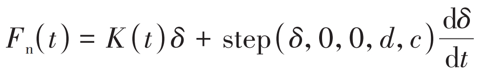
In the formula, K (t) is the contact stiffness coefficient; δ The depth of compression deformation at the contact point; Step is the step function; D is the maximum allowable penetration depth; C is the elastic damping coefficient; D δ/ Dt is the velocity of motion at the contact point.
The calculation formula for meshing force under pitting fault state is:
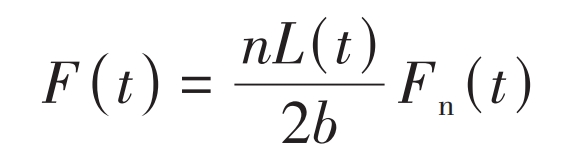
In the formula, n is the number of contact planetary gears; L (t) is the length of the meshing line; B is the tooth thickness.
The calculation formula for the contact stiffness coefficient of the gear teeth is:
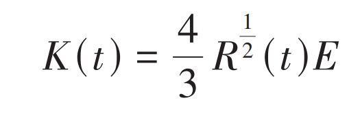
In the formula, R (t) is the comprehensive curvature radius; E is the comprehensive elastic modulus.
According to Hertz contact theory, calculate the depth of compression deformation at the contact point, which is:
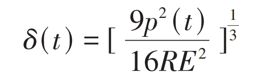
In the formula, p (t) is the normal load at the contact point.
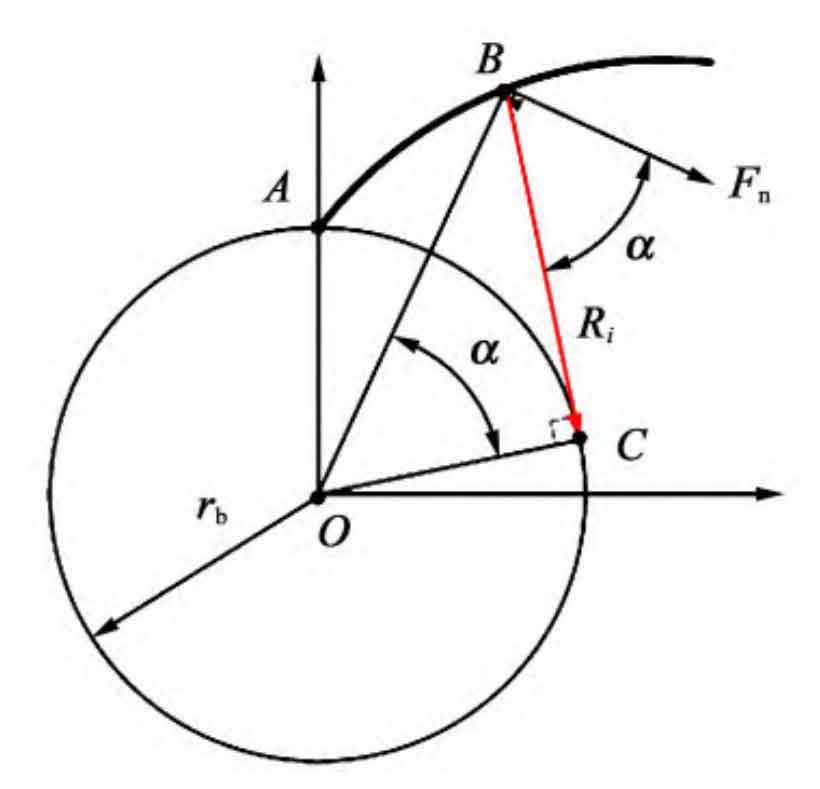
Figure 1 is a schematic diagram of the curvature radius of the involute tooth profile. In Figure 1, ■ AB represents the involute tooth profile. The calculation formula for the comprehensive curvature radius R is:
The formula for calculating the curvature radius of involute spur gears is:
In the formula, rbi (i=1,2) is the radius of the base circle; α (t) The pressure angle at the contact point.
The calculation formula for the comprehensive elastic modulus is:

In the formula, ν 1 ν 2 represents the Poisson’s ratio of the two tooth materials; E1 and E2 are the elastic moduli of the two tooth materials, respectively.
1.2 Calculation of load distribution at meshing points
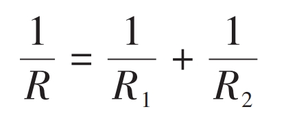
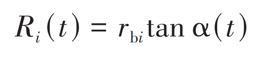
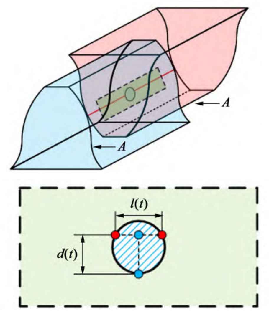
The magnitude of the load affects the compression deformation at the contact point, which is a key variable in calculating the meshing force. When the sun gear fails to mesh, the load distributed on the two meshing teeth is uneven. Therefore, the load can be calculated based on the length of the meshing line of each meshing tooth. The geometric relationship at the occurrence of pitting is shown in Figure 2.
Planetary gear coincidence degree ε The calculation formula is:

In the formula, z1 is the number of teeth on the driving gear; Z2 is the number of driven gear teeth; α AI (i=1,2) is the pressure angle of the tooth tip circle.
The radius of the planetary gear tooth profile at the pitting point is:
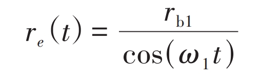
In the formula, ω 1 is the angular velocity of the driving wheel.
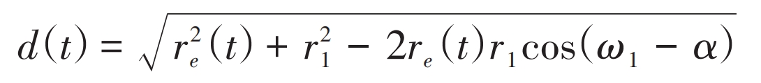
The calculation formula for the distance between two points on the faulty tooth profile is:
The length of the meshing line defect at the pitting tooth is:
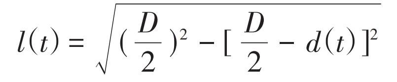
In the formula, D is the maximum diameter of the pitting defect.
Within one meshing cycle, planetary gear meshing is divided into single tooth meshing and double tooth meshing. Considering the defects at the location of planetary gear faults, the entire meshing process is divided into two parts: the first part is the double tooth meshing of planetary gear pairs with no defects on the contact line; The second part is the single tooth meshing of faulty teeth, with pitting pits on the contact line.
The first part of the time and meshing line length are:
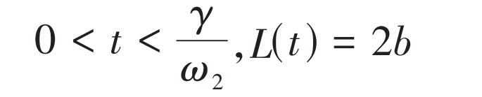
In the formula, ω 2 is the angular velocity of the driven wheel.
The second part of the time and meshing line length are:
In the formula, ri (i=1,2) is the radius of the planetary gear indexing circle; γ I (i=1,2) is the planetary gear angle; N is the number of pitting pits. It is also necessary to consider that when the pit area is large, the faulty tooth is located within the double tooth meshing area, and the faulty point is on the contact line. The tooth profile radius rc at the alternating point of single and double tooth meshing is:
In the formula, ra2 is the radius of the driven gear tooth tip circle.
When re (t)>rc, equation (13) can be rewritten as:
In the formula, PB is the tooth pitch. Figure 3 shows a schematic diagram of mild, moderate, and severe faults simulated based on the number of pits.
2. Dynamic simulation analysis
2.1 Model parameters of planetary gear system
Studying the dynamic response of planetary gear transmission systems requires precise modeling of the research object. Selecting a certain level planetary gear reducer as the research object, first establish a three-dimensional model of the planetary gear system.
The specific parameters of the main components of the planetary gear are shown in Table 1.
| Gear | Number of teeth | Module/mm | Pressure angle/(°) | Displacement coefficient | Material Name |
| Solar wheel | 21 | 2 | 20 | 0 | 20CrMnTi |
| Planetary gear | 31 | 2 | 20 | 0 | 20CrMnTi |
| Ring gear | 84 | 2 | 20 | -0.652 4 | 42Cr |
Draw a three-dimensional assembly model of the planetary gear transmission system based on the parameters of each component of the system. The material properties of each component are shown in Table 2.
| Material Name | Density/(kg/mm^3) | Elastic modulus/(N/mm^2) | Poisson’s ratio |
| 20CrMnTi | 7.8 × 10 ^ -6 | 2.07 x 10 ^ 5 | 0.25 |
| 42Cr | 7.85 x 10 ^ -6 | 2.11 x 10 ^ 5 | 0.3 |
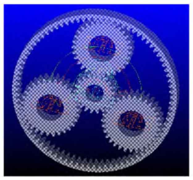
Simulate the drawn planetary gear model using virtual prototyping technology. The simulation model is shown in Figure 4. Add motion pairs and boundary conditions for each part. The calculation formula for the rotational frequency of planetary gears is:
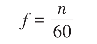
In the formula, n is the rotational speed of the planetary gear. The calculation formula for the meshing frequency of the planetary gears in the sun gear planetary gear section is:
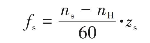
In the formula, ns is the rotational speed of the sun gear; NH is the planetary carrier speed; Zs is the number of teeth on the sun gear.
The input speed of the sun gear is set to 1000 r/min, and the planetary carrier speed is calculated to be 200 r/min according to the planetary gear transmission ratio formula. The contact stiffness coefficient K between the sun gear and planetary gear is 3 045 9 x 10 ^ 5N/mm ^ 3/2. The material collision coefficient is 1.5, and the damping coefficient is 0. of the stiffness coefficient 1%, penetration depth is 0 1 mm; The Coulomb friction method is chosen for friction calculation, and the static friction coefficient of each planetary gear is 0 under the same lubrication conditions 08, the dynamic friction coefficient is 0 05, static resistance slip velocity is 0 1 mm/s, dynamic resistance slip velocity is 10 mm/s. The simulation time is 10 seconds and the number of steps is 100000.
2.2 Dynamic characteristics of planetary gear transmission system under impact conditions
Analyze the dynamic response of planetary gear transmission system under impact load excitation. Apply pulsed load torque on the planetary carrier to simulate impact conditions, while simulating stable loads on the planetary carrier during equipment operation. The two excitations are opposite to the rotation direction of the planetary carrier.
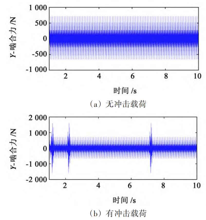
Under the impact load, the dynamic response of the planetary gear transmission system is shown in Figure 5. When there is no impact load excitation, the meshing force between the sun gear and planetary gear fluctuates steadily within a certain range, and the time difference between adjacent peak values is 0 003 6 seconds corresponds to 1 meshing cycle. Under the influence of impact load, the meshing force increases with the increase of impact load.
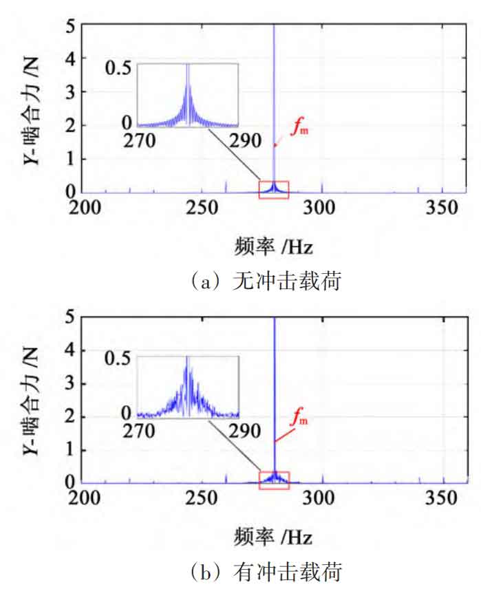
The frequency domain diagram of the meshing force signal obtained by processing the simulation signal using FFT is shown in Figure 6. Due to load fluctuations, there are significant amplitudes on both sides of the meshing frequency in the simulation signal. This is due to the intensification of time-domain signal fluctuations caused by the impact load, resulting in more amplitudes in the low-frequency region of the frequency domain. Therefore, modulation sidebands with intervals of this low-frequency value appear on both sides of the meshing frequency.
2.3 Time and frequency domain analysis of planetary gear transmission system with pitting fault
The meshing force between tooth surfaces can cause the metal on the surface of planetary gears to detach, resulting in fatigue small pits. According to Luo et al.’s research, pitting corrosion faults are prone to occur at the meshing pitch lines of planetary gears.
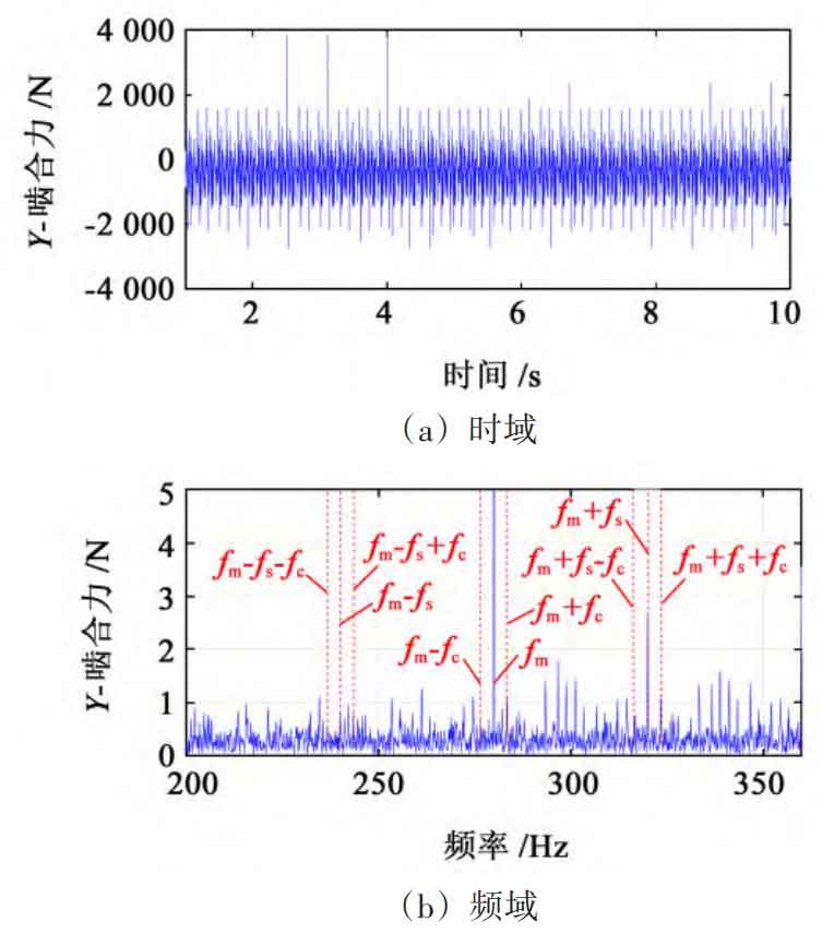
Perform time-domain and frequency-domain analysis on the radial meshing force of the sun gear planetary gear under pitting corrosion fault, and the simulation results are shown in Figure 7. Due to the fault defect of the planetary gear, the meshing stiffness of the planetary gear decreases. At this time, the vibration of the contact tooth surface between the faulty gear teeth and the planetary gear increases, leading to an increase in meshing force. The interval between two adjacent fault impacts is 0 025 seconds, corresponding to the time interval between the two contacts between the fault point and the planetary gear, which corresponds to a fault characteristic frequency of 40 Hz. Analyzing Figure 7, it can be seen that the peak frequency is 280 Hz, corresponding to the planetary gear meshing frequency. Comparing the frequency domain of the fault free meshing force signal, it was found that pitting faults cause an increase in the characteristic frequencies on both sides of the planetary gear meshing frequency. There is a 40 Hz interval difference in the sidebands on both sides of the meshing frequency, and there are sidebands with planetary carrier rotation frequency as the interval on both sides of the relative rotation frequency of the sun gear.
2.4 Identification of planetary gear transmission system faults with varying degrees of pitting corrosion under impact conditions
Analyze the dynamic response under different degrees of fault. As observed earlier, in the time domain, impact loads and pitting faults can cause significant fluctuations in the time domain, leading to inaccurate statistical indicators of the time domain signal; In the frequency domain, impact loads and pitting faults can cause an increase in meshing frequency, relative rotation frequency of the sun gear, and the sideband components on both sides of its harmonics. However, the variation in sideband energy is relatively small compared to the total signal energy. Therefore, the energy index SC of the sideband centroid is introduced to observe and identify faults, namely:
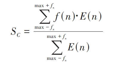
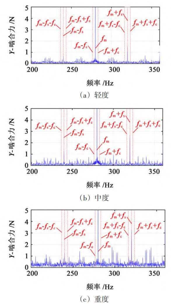
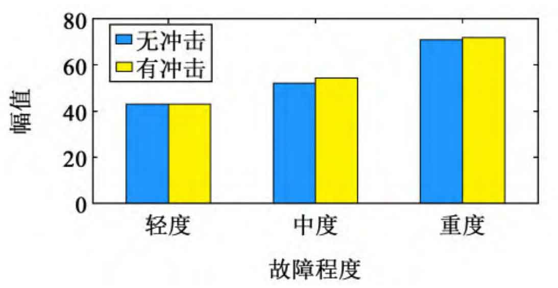
In the formula, f (n) is the frequency domain amplitude; E (n) is the distance from the corresponding point to the origin of the spectrum. This indicator can effectively observe important information on frequency distribution and energy distribution, therefore, it is introduced into the monitoring of vibration signals. The frequency domain characteristics of planetary gear transmission systems containing varying degrees of pitting faults under impact conditions are shown in Figure 8. Generate sidebands with fault characteristic frequencies as intervals on both sides of the meshing frequency; As the severity of the fault intensifies, the edge frequency bandwidth on both sides of the fault characteristic frequency increases, and the amplitude of the edge frequency band shows a significant increase. Calculate the energy of the center of mass of the sideband, as shown in Figure 9. As shown in Figure 9, with the increase of fault severity, the energy of the center of mass in the sideband increases, and the indicators under the same fault severity are similar, indicating that this indicator is minimally affected by the impact load.
3. Experimental analysis of pitting failure
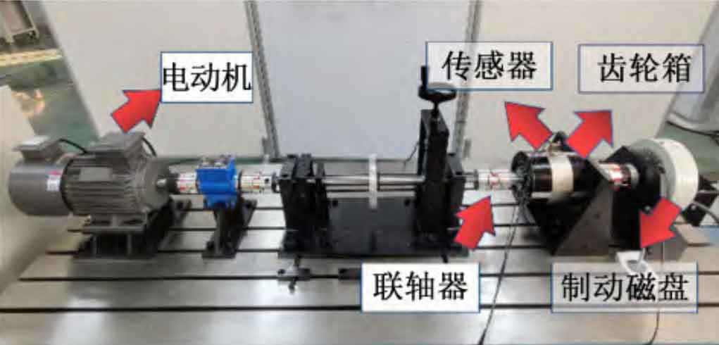
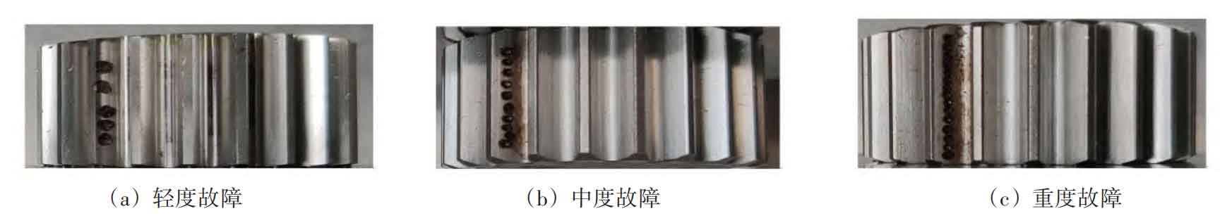
Conduct experiments on planetary gears containing varying degrees of pitting faults as described in Section 2.4. As shown in Figure 10, the 2K-H planetary gearbox was selected as the experimental target and installed horizontally. The test bench consists of an electric motor, coupling, planetary gearbox, three-way vibration and speed sensor, photoelectric encoder, and brake disk. The number of sun gear teeth in the planetary gearbox is 21, the number of teeth in all three planetary gears is 31, the number of teeth in the ring gear is 84, and the modulus is 2 mm. Use accelerometer to collect data. Sensors are attached to the box directly above the sun gear to collect radial vibration signals from the system. The acquisition software is HD-9200, the experimental sampling frequency is f=61 440 Hz, and the number of sampling points is 307 200. Using laser engraving technology to process 5, 10, and 15 circular pits of the same size near the tooth profile, simulating mild, moderate, and severe faults of planetary gears. The faulty planetary gear is shown in Figure 11.
In the experiment, magnetic powder brakes were used to control load changes. During the experiment, multiple impact loads were applied as the fault diagnosis background for the planetary gear transmission system. The impact conditions were simulated to verify that the energy index of the edge belt center of mass can accurately serve as the basis for fault diagnosis under the impact conditions.
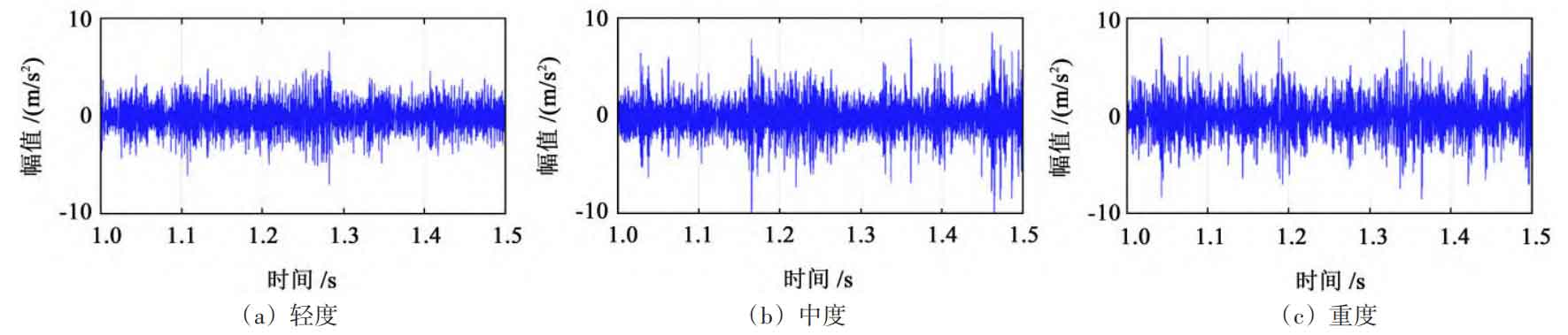
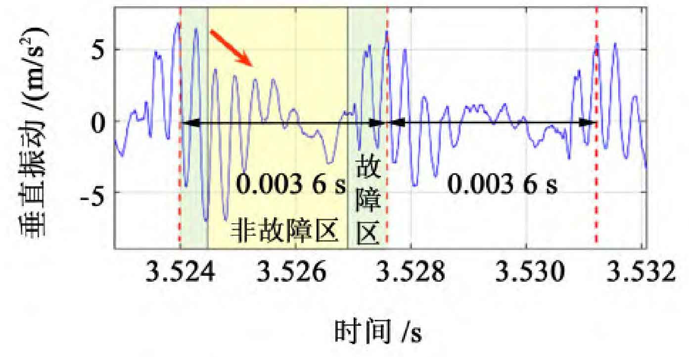
Observing the time-domain signals of vertical vibration acceleration of planetary gears with different degrees of fault as shown in Figure 12, it can be clearly observed that due to the impact load, the vibration amplitude increases; As the degree of fault increases, the amplitude of signal fluctuations continues to increase. Among them, the fluctuation amplitude of mild faults is 2 5 m/s ^ 2, moderate fault fluctuation amplitude reaches 3 m/s ^ 2, and severe fault fluctuation amplitude is 3 8 m/s ^ 2.
Fault shock and meshing shock can be distinguished from the signal. As shown in Figure 13, when the faulty tooth begins to mesh, the fluctuation increases. When the faulty point on the faulty tooth meshes, the fluctuation reaches its peak and gradually weakens until it stabilizes. Therefore, the fault impact caused by fault excitation is significantly stronger than the meshing impact caused by changes in the number of meshing teeth of planetary gears.
Analyzing the frequency domain diagrams of planetary gear systems with different degrees of fault as shown in Figure 14, it can be seen that there are planetary carrier rotation frequencies (fc) 3 on both sides of the meshing frequency 4 Hz and fault characteristic frequency (fs) 39 A sideband with an interval of 8 Hz.
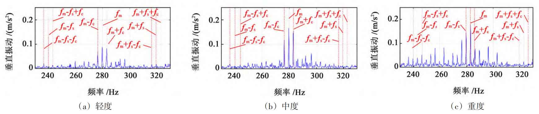
On both sides of the fault characteristic frequency, there is also modulation of the planetary carrier rotation frequency. Due to the influence of signal frequency modulation, it is difficult to observe a direct relationship between amplitude changes and fault severity. The use of sideband centroid energy indicators can distinguish different degrees of faults. Conduct three sets of experiments for each scenario to improve the reliability of the experimental results.
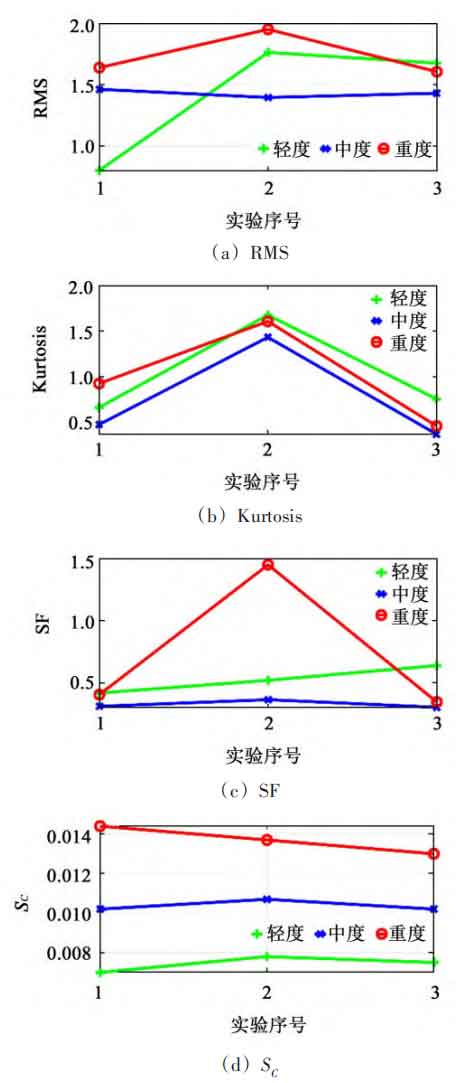
The statistical characteristics of the experimental signal of planetary gears are shown in Figure 15. Three experiments were conducted on each level of malfunction to reduce the randomness of the experimental results. By comparison, it can be seen that the statistical values of Root Mean Square (RMS) at different fault levels do not have independent regional ranges, so it is impossible to distinguish the degree of fault; Both Shape Factor (SF) and Kurtosis cannot indicate changes in the degree of failure. The energy value SC of the sideband centroid proposed in this article can effectively distinguish the fault interval, and its value increases with the degree of fault.
4. Conclusion
A dynamic model of the planetary gear system with pitting fault under impact conditions was established, and the dynamic characteristics of the planetary gear system under impact conditions were studied through simulation calculations. The following conclusions were obtained:
1) The impact load will instantly excite the meshing force of the planetary gear, thereby intensifying the fluctuation of the angular acceleration of the planetary carrier; And as the impact increases, the vibration becomes more intense. Due to the impact load, smaller sideband modulation frequencies appear on both sides of the meshing frequency.
2) The pitting fault of the planetary gear system can cause periodic fluctuations in the vibration signal, with a periodic interval of the time difference between two adjacent contacts with the planetary gear teeth at the fault point. In the frequency domain, the low-frequency region will generate characteristic frequencies corresponding to this time difference. On both sides of the meshing frequency, there exists a sideband with this characteristic frequency as the difference, that is, the modulation of the fault characteristic frequency by the meshing frequency. As the degree of fault increases, the overall amplitude of the sidebands on both sides increases.
3) Experimental results have shown that the energy index of the center of mass of the sideband can effectively identify the degree of planetary gear failure under impact conditions.