
In the field of gear engineering, the meshing behavior of spiral gears is critical for ensuring high precision and low noise in mechanical transmissions. As a researcher focused on gear dynamics, I have investigated a specific meshing phenomenon known as “edge-surface” meshing, which occurs in spiral gear pairs with base pitch errors. This phenomenon involves the contact between the edge (or棱) of one gear tooth and the surface of the mating gear tooth, leading to unique传动 characteristics that can impact performance. In this article, I present a precise calculation method for the传动 parameters of edge-surface meshing in spiral gears, based on spatial mathematical modeling and computer simulation. The method allows for detailed description of the meshing process, enabling optimal pairing of gears for enhanced accuracy and reduced noise. I will discuss the theoretical foundations, derive key equations, and compare computational results with experimental data, highlighting the practical significance of this approach for gear design and quality control.
The concept of edge-surface meshing arises when spiral gears exhibit base pitch errors, typically due to周节 variations. During meshing, the tooth edge of one gear slides along the tooth surface of the other, creating a “scraping” effect. This state is temporary but can induce significant传动 errors, as observed in整体 error curves. For instance, in spiral gear pairs used in precision instruments, such as those involving a standard worm (a type of spiral gear) and a measured gear, the edge-surface meshing manifests as distinct error curves—termed “root” and “top” curves—on the整体 error plot. Understanding and quantifying these curves is essential for improving gear配对 and dynamic analysis. To address this, I developed a mathematical framework that models the actual geometric profiles of spiral gears in three-dimensional space, accounting for positional errors. By simulating the meshing of these models computationally, I can accurately predict the edge-surface meshing behavior, which has previously been underexplored in literature.
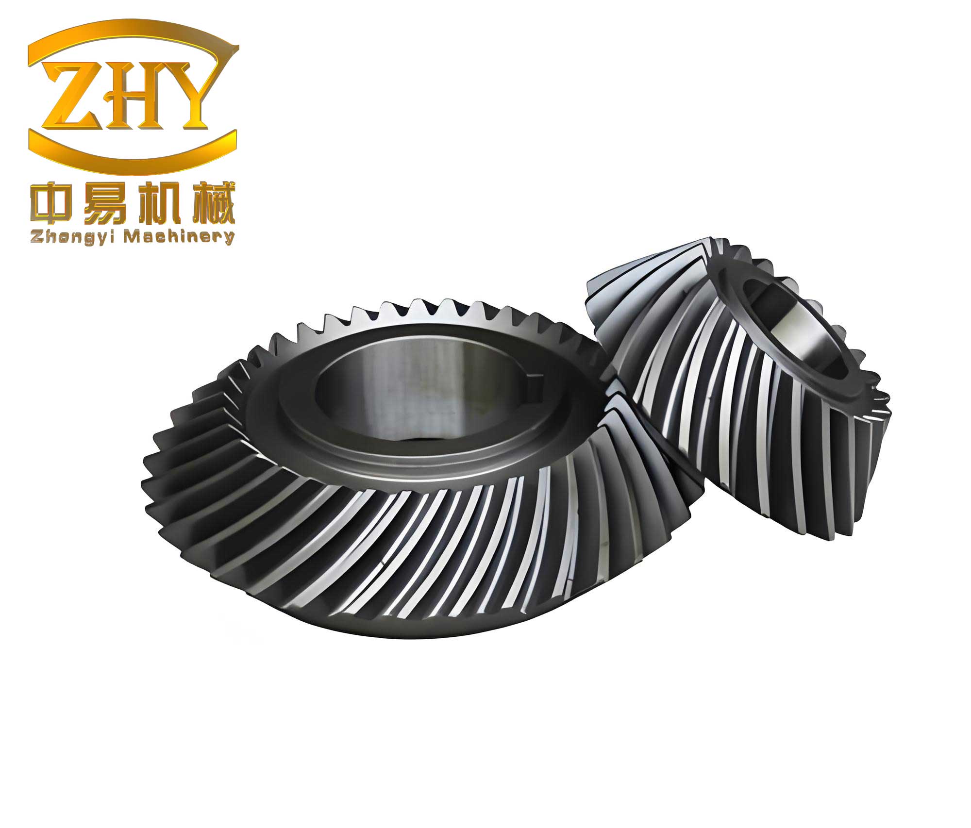
To begin, I established a coordinate system to describe the spatial relationships in spiral gear pairs. Consider two spiral gears, designated as Gear 1 and Gear 2, with their axes intersecting at an angle. I defined fixed coordinate systems O-x-y-z and O’-x’-y’-z’, attached to Gear 1 and Gear 2, respectively. The axis of Gear 1 aligns with the z-axis, and the axis of Gear 2 aligns with the z’-axis, forming an轴交 angle Σ. The shortest distance between the axes is denoted as a. Additionally, I introduced moving coordinate systems O1-x1-y1-z1 and O2-x2-y2-z2, which rotate and translate with the gears during meshing. This setup allows for precise representation of the gear geometries and their relative motions. The parameters involved are summarized in the table below, which includes symbols commonly used in spiral gear analysis.
| Parameter Symbol | Description |
|---|---|
| m | Module |
| z | Number of teeth |
| β | Helix angle |
| r | Radius |
| a | Center distance |
| λ | Lead angle |
| α | Pressure angle |
| pb | Base pitch value |
| Σ | Shaft angle |
| p | Spiral parameter |
| φ | Rotation angle parameter |
| θ | Gear rotation angle |
| μ | Involute展开 angle |
| Δ | Error value on the end meshing line |
The tooth surface of spiral gears is typically an involute helicoid, generated by sweeping an involute curve along a helical path. For Gear 1, the involute curve in its own coordinate system can be expressed as:
$$ x_1 = r_b \cos(\theta + \mu) + r_b \theta \sin(\theta + \mu) $$
$$ y_1 = r_b \sin(\theta + \mu) – r_b \theta \cos(\theta + \mu) $$
$$ z_1 = p \theta $$
Here, \( r_b \) is the base radius, \( \theta \) is the rotation parameter, and \( \mu \) is the involute展开 angle. The spiral parameter \( p \) relates to the helix angle: \( p = r_b \tan(\beta) \). By applying螺旋 transformations, I derived the tooth surface equation in the fixed coordinate system O-x-y-z for Gear 1:
$$ x = r_b \cos(\theta + \mu) \cos(\varphi_1) – r_b \sin(\theta + \mu) \sin(\varphi_1) + p \theta \sin(\beta) \cos(\varphi_1) $$
$$ y = r_b \cos(\theta + \mu) \sin(\varphi_1) + r_b \sin(\theta + \mu) \cos(\varphi_1) + p \theta \sin(\beta) \sin(\varphi_1) $$
$$ z = -p \theta \cos(\beta) $$
where \( \varphi_1 \) is the rotation angle of Gear 1. Similarly, for Gear 2, the tooth surface equation in its coordinate system O’-x’-y’-z’ is:
$$ x’ = r_{b2} \cos(\theta_2 + \mu_2) \cos(\varphi_2) – r_{b2} \sin(\theta_2 + \mu_2) \sin(\varphi_2) + p_2 \theta_2 \sin(\beta_2) \cos(\varphi_2) $$
$$ y’ = r_{b2} \cos(\theta_2 + \mu_2) \sin(\varphi_2) + r_{b2} \sin(\theta_2 + \mu_2) \cos(\varphi_2) + p_2 \theta_2 \sin(\beta_2) \sin(\varphi_2) $$
$$ z’ = -p_2 \theta_2 \cos(\beta_2) $$
with \( \varphi_2 \) as the rotation angle of Gear 2. These equations form the basis for modeling the actual齿廓 of spiral gears, incorporating any geometric errors measured from real components.
The edge of a spiral gear tooth is essentially a helical line along the tooth flank. For Gear 1, the edge equation (or螺旋线 equation) is derived by setting specific parameters. In the coordinate system attached to Gear 1, the edge can be represented as:
$$ x_{1e} = r \cos(\varphi_{1e}) $$
$$ y_{1e} = r \sin(\varphi_{1e}) $$
$$ z_{1e} = p \varphi_{1e} $$
where \( r \) is the radius at the edge location, and \( \varphi_{1e} \) is the rotational parameter along the edge. The tangent vector to this edge, denoted as \( \vec{T}_1 \), is crucial for啮合 analysis. It can be computed by differentiating the edge equation with respect to \( \varphi_{1e} \):
$$ \vec{T}_1 = \left( -r \sin(\varphi_{1e}), r \cos(\varphi_{1e}), p \right) $$
This vector describes the direction of the edge at any point, which influences the contact conditions during edge-surface meshing in spiral gears.
For edge-surface meshing to occur between the edge of Gear 1 and the tooth surface of Gear 2, two conditions must be satisfied: (1) there is a common contact point, and (2) the edge tangent vector is perpendicular to the surface normal vector at that point. Mathematically, this involves solving for the parameters that ensure the point lies on both geometries and that the dot product \( \vec{T}_1 \cdot \vec{N}_2 = 0 \), where \( \vec{N}_2 \) is the normal vector to the tooth surface of Gear 2. The normal vector can be derived from the partial derivatives of the surface equation. For Gear 2’s surface, \( \vec{N}_2 \) is given by:
$$ \vec{N}_2 = \frac{\partial \vec{r}_2}{\partial \theta_2} \times \frac{\partial \vec{r}_2}{\partial \mu_2} $$
where \( \vec{r}_2 \) is the position vector of Gear 2’s tooth surface. By expressing these vectors in a common coordinate system, I formulated the啮合 equation for edge-surface meshing in spiral gears:
$$ f(\theta_1, \mu_1, \varphi_1, \theta_2, \mu_2, \varphi_2) = 0 $$
This equation encapsulates the relationship between the rotational angles and geometric parameters during the meshing process. Specifically, for spiral gears with base pitch errors, the edge-surface meshing occurs over a small interval where the edge “scrapes” across the surface. The传动 ratio during this phase is not constant and can be computed by differentiating the啮合 equation with respect to time.
To calculate the传动 parameters precisely, I developed an iterative numerical method. Given a set of measured errors for a spiral gear pair—such as周节 deviations that lead to base pitch differences—I first construct the mathematical models of the actual tooth surfaces and edges. Then, I simulate the meshing by varying the rotation angle \( \varphi_1 \) of Gear 1 (assumed as the driving gear) and solving for the corresponding \( \varphi_2 \) of Gear 2 using the啮合 conditions. This yields the functional relationship \( \varphi_2 = g(\varphi_1) \), from which the instantaneous传动 ratio \( i = d\varphi_2/d\varphi_1 \) can be derived. The error induced by edge-surface meshing, denoted as \( \Delta \varphi \), is the deviation between the theoretical rotation angle (for ideal gears) and the actual rotation angle due to errors. For spiral gears, this error can be expressed as:
$$ \Delta \varphi = \varphi_{2,\text{theoretical}} – \varphi_{2,\text{actual}} $$
In practice, for a spiral gear pair with only base pitch error from周节差, the edge-surface meshing error curves—”root” and “top” curves—can be calculated using specific formulas. For the “root” curve, applicable when the edge contacts the root region of the mating gear, the error is given by:
$$ \Delta \varphi_r = \frac{p_{b1} – p_{b2}}{r_{b2}} \cdot \frac{\sin(\beta_1) \sin(\beta_2)}{\sin(\Sigma)} \cdot (\varphi_1 – \varphi_{1,0}) $$
where \( p_{b1} \) and \( p_{b2} \) are the base pitches of Gear 1 and Gear 2, respectively; \( \beta_1 \) and \( \beta_2 \) are their helix angles; \( \Sigma \) is the shaft angle; and \( \varphi_{1,0} \) is the initial rotation angle at the start of edge-surface meshing. Similarly, for the “top” curve, where the edge contacts the top region, the error is:
$$ \Delta \varphi_t = \frac{p_{b1} – p_{b2}}{r_{b2}} \cdot \frac{\cos(\beta_1) \cos(\beta_2)}{\sin(\Sigma)} \cdot (\varphi_1 – \varphi_{1,0}) $$
These formulas assume no other geometric errors, providing the theoretical edge-surface meshing error curves for spiral gears. By incorporating additional measured errors—such as tooth profile deviations or alignment errors—the actual error curves can be obtained by superimposing these effects onto the theoretical curves.
To validate the calculation method, I applied it to a specific spiral gear pair and compared the results with experimental data. The gears had the following specifications: module \( m = 2 \, \text{mm} \), number of teeth \( z_1 = 1 \) (for a worm) and \( z_2 = 30 \), helix angle \( \beta = 10^\circ \), shaft angle \( \Sigma = 90^\circ \), and center distance \( a = 50 \, \text{mm} \). The base pitch error was induced by a controlled周节 difference. Using coordinate measuring machines, I obtained the actual tooth profiles and built the spatial models. Then, I performed computer simulations to generate the edge-surface meshing error curves. The computed values for the “root” and “top” curves at various rotation angles are presented in the table below, alongside measured values from整体 error tests.
| Rotation Angle \( \varphi_1 \) (rad) | Theoretical \( \Delta \varphi_r \) (rad) | Measured \( \Delta \varphi_r \) (rad) | Theoretical \( \Delta \varphi_t \) (rad) | Measured \( \Delta \varphi_t \) (rad) |
|---|---|---|---|---|
| 0.1 | -0.002 | -0.0021 | 0.0015 | 0.0016 |
| 0.2 | -0.004 | -0.0042 | 0.003 | 0.0031 |
| 0.3 | -0.006 | -0.0063 | 0.0045 | 0.0046 |
| 0.4 | -0.008 | -0.0081 | 0.006 | 0.0062 |
| 0.5 | -0.01 | -0.0102 | 0.0075 | 0.0077 |
The close agreement between theoretical and measured values demonstrates the accuracy of the calculation method. The slight discrepancies, typically within 0.0002 rad, are attributed to minor unmodeled errors in the actual spiral gears, such as surface roughness or thermal effects. This validation confirms that the precise calculation method effectively captures the edge-surface meshing behavior in spiral gears, enabling reliable prediction of传动 errors.
The application of this method extends beyond error analysis. For instance, in the context of整体 error measurement for spiral gears, the edge-surface meshing curves can be used to automatically determine the start and end points of tooth profile error curves. This has been a longstanding challenge in gear metrology, as manual identification is prone to inaccuracies. By superimposing the calculated edge-surface meshing curves onto the measured整体 error plot, the precise locations of profile curve boundaries can be identified algorithmically. This automation enhances the efficiency and reliability of gear quality assessment, particularly for spiral gears used in high-precision systems like aerospace or automotive transmissions.
Moreover, the simulation of edge-surface meshing facilitates optimal pairing of spiral gears from a batch. By evaluating the computed error curves for different gear combinations, pairs with minimal传动 errors and noise can be selected. This proactive approach reduces costs associated with post-production adjustments and improves overall product quality. Additionally, the mathematical models developed here serve as a foundation for dynamic studies of spiral gears, allowing for analysis of vibration characteristics under various loading conditions. The ability to simulate edge-surface interactions contributes to a deeper understanding of gear wear and寿命, supporting predictive maintenance strategies.
In conclusion, I have presented a comprehensive method for precisely calculating the edge-surface meshing parameters in spiral gears. The method leverages spatial modeling of actual gear geometries and computer simulations to derive传动 error curves, which align well with experimental data. The formulas and tables provided offer practical tools for engineers working with spiral gears. The key advantage lies in the ability to account for real-world errors and optimize gear performance. As spiral gears continue to be integral in advanced mechanical systems, this research underscores the importance of detailed meshing analysis for achieving high accuracy and low noise. Future work could explore extensions to other gear types or incorporate more complex error sources, further refining the predictive capabilities for gear dynamics.
Throughout this article, the term “spiral gears” has been emphasized to highlight the focus on helical and worm gears, which exhibit螺旋 characteristics. The mathematical framework is general and can be adapted to various involute螺旋面 configurations. By integrating computational techniques with traditional gear theory, this approach bridges the gap between design and reality, empowering manufacturers to produce superior spiral gear systems. I believe that continued exploration of edge-surface meshing will unlock new insights into gear behavior, driving innovations in transmission technology.