
The performance, durability, and NVH (Noise, Vibration, and Harshness) characteristics of automotive drivetrains are profoundly influenced by the quality of the gear mesh. In rear-wheel-drive configurations, the hypoid gear set within the final drive assembly is a critical component, and the geometry and positioning of its contact pattern under load are paramount. Achieving a consistent and optimal contact pattern after the final manufacturing step—heat treatment—presents a significant challenge due to the inherent and often unpredictable distortions induced by thermal and phase transformation stresses. This article, based on our extensive research and practical implementation, details a systematic methodology for analyzing, predicting, and controlling post-heat-treatment contact pattern shifts in hypoid gears. Our approach hinges on understanding the fundamental relationship between relative tooth surface errors and contact zone migration, enabling proactive compensation during the gear cutting stage to ensure final quality.
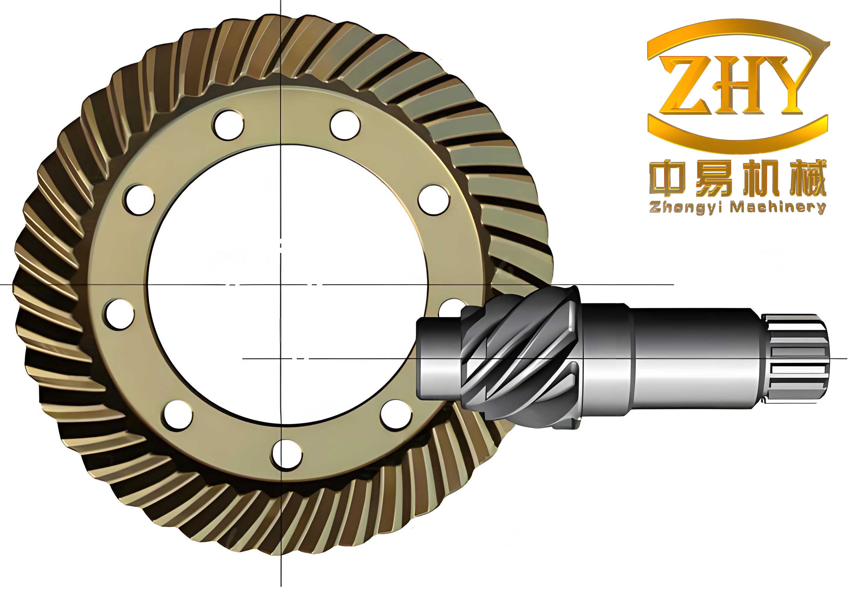
Heat treatment, essential for achieving the required surface hardness and core toughness in hypoid gears, is a major source of geometric distortion. The non-uniform heating and cooling cycles generate complex thermal gradients and associated stresses, compounded by volumetric changes during martensitic transformation. These effects cause deviations in the meticulously machined tooth flanks of both the pinion (drive gear) and the gear (driven gear). While absolute control over every instance of distortion is impractical, we have observed that for a given batch processed under identical heat treatment conditions, the pattern of change in specific tooth flank errors is remarkably consistent. To quantify this, we analyzed a sample batch of 27 hypoid gear sets, measuring key flank error parameters—specifically, spiral angle error ($$ \Delta \beta $$) and pressure angle error ($$ \Delta \alpha $$)—both before and after carburizing and quenching.
The data revealed a clear and repeatable trend. The pressure angle error for specific working flanks increased systematically; for instance, the pinion convex flank pressure angle error increased by approximately 5 arc-minutes, and the gear concave flank error increased by about 7 arc-minutes. Post-heat-treatment, these errors stabilized around new mean values. More critically for contact pattern control, the spiral angle errors exhibited a distinct and consistent reduction. The pinion convex flank spiral angle decreased by an average of about 3 arc-minutes, while the gear concave flank spiral angle decreased more significantly. The statistical summary of the post-heat-treatment spiral angle error change is presented below:
| Flank Description | Mean Change in Spiral Angle Error (arc-min) | Variance (arc-min²) | Observed Range (arc-min) |
|---|---|---|---|
| Pinion Convex Flank ($$ \Delta \beta_{pt} $$) | -2.14 | 0.14 | -1.96 to 2.47 |
| Gear Concave Flank ($$ \Delta \beta_{ga} $$) | -7.25 | 0.55 | -8.01 to -6.03 |
This consistent distortion pattern indicates that while pressure angle errors shift to a new stable state, their influence on the contact pattern’s centroid is largely fixed for a given process. The primary driver for unpredictable and undesirable contact pattern shifts post-heat-treatment is, therefore, the variation in relative spiral angle error between the mating pinion and gear flanks. Consequently, controlling the quality of hypoid gears after heat treatment necessitates a focus on managing this relative spiral error.
The core of our methodology is the application of first-order relative tooth surface error theory to model contact pattern偏移. We define the relative errors between a mating pair of flanks. For the drive side (often pinion convex vs. gear concave), the relative pressure angle error ($$ \alpha_a $$) and relative spiral angle error ($$ \beta_a $$) are given by:
$$ \alpha_a = \Delta \alpha_{pt} – \Delta \alpha_{ga} $$
$$ \beta_a = \Delta \beta_{pt} – \Delta \beta_{ga} $$
where the subscripts $$ pt $$ and $$ ga $$ denote pinion convex flank and gear concave flank errors, respectively. Similarly, for the coast side (pinion concave vs. gear convex), relative errors $$ \alpha_t $$ and $$ \beta_t $$ are defined. The impact of these relative errors on the contact pattern can be understood by analyzing the effective clearance or mismatch between the two theoretical flanks when one is modified by the error. Consider a 45-point topological grid (5 points along the profile height, 9 points along the length) measured on the actual flanks after heat treatment. We can define average relative clearances at key zones.
To analyze the effect of relative spiral angle error ($$ \beta $$), we calculate the average clearance at the heel (large end, index j=9) and toe (small end, index j=1) across the profile height:
$$ L_H = \frac{\sum_{i=1}^{5} L(i, 9)}{5}, \quad L_T = \frac{\sum_{i=1}^{5} L(i, 1)}{5} $$
where $$ L(i,j) $$ is the local normal deviation or clearance between the flanks at grid point (i,j). A positive relative spiral angle error ($$ \beta_a > 0 $$), which occurs if the pinion convex spiral angle becomes more negative or the gear concave spiral angle becomes more positive relative to each other, increases the effective clearance at the heel ($$ L_H $$ increases to $$ L’_H $$) and decreases it at the toe ($$ L_T $$ decreases to $$ L’_T $$). During meshing under load, areas with reduced clearance will contact earlier or more heavily. Therefore, an increase in $$ \beta_a $$ causes the contact pattern on the gear concave flank to shift towards the toe. Conversely, an increase in the coast side relative spiral error $$ \beta_t $$ shifts the gear convex flank contact pattern towards the heel.
The effect of relative pressure angle error ($$ \alpha $$) is analyzed by examining clearances at the tip and root zones across the face width:
$$ L_{F-T} = \frac{\sum_{j=1}^{9} L(1, j)}{9}, \quad L_{T-F} = \frac{\sum_{j=1}^{9} L(5, j)}{9} $$
where $$ L_{F-T} $$ represents the clearance between the pinion tip and gear root, and $$ L_{T-F} $$ represents the clearance between the pinion root and gear tip. An increase in relative pressure angle error $$ \alpha_a $$ decreases $$ L_{F-T} $$ and increases $$ L_{T-F} $$, causing the contact pattern to shift towards the root of the gear tooth. The governing rules for contact pattern shift in hypoid gears due to heat treatment-induced relative errors are summarized as follows:
| Relative Error | Increase in Error Value Causes Contact Pattern Shift |
|---|---|
| Drive side relative spiral error ($$ \beta_a $$) | Gear concave flank pattern shifts towards the toe. |
| Coast side relative spiral error ($$ \beta_t $$) | Gear convex flank pattern shifts towards the heel. |
| Drive side relative pressure error ($$ \alpha_a $$) | Gear concave flank pattern shifts towards the root. |
| Coast side relative pressure error ($$ \alpha_t $$) | Gear convex flank pattern shifts towards the top. |
To empirically validate this theory and establish quantitative guidelines for our specific hypoid gear production, we conducted a designed experiment. The goal was to observe the contact pattern position resulting from different magnitudes of post-heat-treatment relative spiral angle error on the critical drive side. A single pinion with a convex flank spiral angle error of approximately -2 arc-minutes was selected. Three groups of gears, with heat-treated concave flank spiral angle errors averaging approximately -6, -7, and -8 arc-minutes, were paired with this pinion for rolling tests. The tests were performed on a computer-controlled rolling test machine under standardized conditions (5 N·m load, 0.1 mm backlash, 200 RPM). The resulting contact patterns on the gear concave flanks were recorded and analyzed.
The experimental results provided clear visual and quantitative confirmation of the theoretical model. With the pinion error fixed at ~-2′, the relative spiral error $$ \beta_a $$ increased from ~4′ (for $$ \Delta \beta_{ga} $$ = -6′) to ~5′ (for -7′) and ~6′ (for -8′). The observed contact patterns systematically migrated from an acceptable mid-toe position towards, and eventually off, the toe edge of the tooth. This direct correlation validated our use of first-order relative spiral angle error as a primary predictor for post-heat-treatment contact pattern location in hypoid gears. Furthermore, it established a practical control limit: for this specific gear design and heat treatment process, maintaining the heat-treated gear concave spiral angle error at -6 arc-minutes or less (resulting in $$ \beta_a \leq 4′ $$) was necessary to keep the contact pattern within the desired mid-toe region.
Armed with the understanding of the distortion规律 and the verified contact pattern偏移原理, the logical step for quality control is proactive compensation. Given the high cost and complexity of post-heat-treatment grinding for mass-produced automotive hypoid gears, the most effective strategy is to modify the cutting process to anticipate and offset the expected distortion. This method, known as cutting compensation, involves creating a new “pre-distorted” theoretical tooth model for the gear cutting machine. The model is adjusted so that after the predictable heat treatment distortion occurs, the final tooth geometry aligns with the original design intent.
Our focus, based on the earlier analysis, was the spiral angle error. The data showed the gear concave flank spiral angle consistently decreased by about 7 arc-minutes. To achieve a final error of ≤ -6′, the pre-heat-treatment (cut) error needed to be around +1′. Therefore, we iteratively adjusted the machine settings for cutting the gear concave flank, intentionally introducing a positive spiral angle error. After several trials, a new stable cutting setup was established, targeting this compensated geometry. To validate the effectiveness of this new cutting model, a production batch of 360 gear sets was manufactured using the compensated program. A statistically sampled subset of 27 pinions and 27 gears was tracked through heat treatment and then inspected for final flank errors.
The post-heat-treatment inspection results confirmed the success of the compensation strategy. The spiral angle errors of the sampled hypoid gears were now distributed within the targeted range, as shown in the summary below:
| Flank Description | Mean Spiral Angle Error After HT (arc-min) | Variance (arc-min²) |
|---|---|---|
| Pinion Convex Flank | -2.14 | 0.09 |
| Gear Concave Flank | -5.33 | 0.53 |
The distribution of gear concave flank errors was tightly clustered between -4′ and -6′, a significant improvement over the previous -8′ to -6′ range and well within the control limit. The final and most critical validation step was rolling tests. Gears with post-heat-treatment concave spiral angle errors of approximately -6′, -5′, and -4′ were paired with standard pinions. The resulting contact patterns were all located stably in the mid-toe region, demonstrating successful control. The contact pattern was no longer biased to the toe edge, confirming that the proactive cutting compensation for heat treatment distortion had effectively solved the quality issue. This systematic approach—rooted in the analysis of relative tooth surface errors, validated by controlled experiment, and implemented via process compensation—provides a robust framework for ensuring the consistent quality of hypoid gears in high-volume manufacturing. It transforms heat treatment distortion from an unpredictable variable into a manageable, compensatable factor in the production of precision hypoid gears.
The implications of this methodology extend beyond the specific case study. The principle of using first-order relative flank error analysis provides a powerful diagnostic tool for troubleshooting contact pattern issues in hypoid gears. By measuring the spiral and pressure angle errors on a problematic gear set, engineers can quickly determine whether a pattern shift is due to a pinion error, a gear error, or a mismatch between them. Furthermore, the compensation strategy is not limited to spiral angle. While it was the dominant factor in our case, the same logic can be applied to pressure angle errors or even higher-order corrections if the distortion pattern warrants it. The key is establishing a reliable correlation between pre- and post-heat-treatment geometry for a stable manufacturing process. For new hypoid gear designs or changes in heat treatment facilities, a similar characterization study is essential to build the compensation database. Advanced statistical process control (SPC) can then be applied to the cutting process parameters to ensure the pre-heat-treatment geometry remains within the tolerance band required to yield good final contact patterns. This data-driven approach minimizes scrap, reduces reliance on post-process corrective grinding, and ultimately enhances the performance and reliability of the final drive unit containing the hypoid gears.
In conclusion, controlling the contact pattern in hypoid gears after heat treatment is a multi-faceted challenge that requires a deep understanding of metallurgical effects, gear geometry, and manufacturing systems. We have demonstrated that the seemingly random distortion can be decomposed into consistent systematic shifts in key flank error parameters. By focusing on the relative spiral angle error between mating flanks, we developed a predictive model for contact pattern migration. Experimental validation solidified this model and established practical control limits. Finally, by embedding this knowledge into the gear cutting process through proactive compensation, we successfully produced hypoid gears that consistently met quality standards after heat treatment. This end-to-end methodology underscores the importance of integrated process engineering in achieving precision in complex mechanical components like hypoid gears, ensuring their critical role in vehicle dynamics and NVH performance is reliably fulfilled.