
The pursuit of high-performance gear transmissions necessitates not only superior accuracy but also controlled modifications to the tooth flank topography. Topological modifications, encompassing intentional deviations from the ideal involute profile and lead, are crucial for optimizing contact patterns, reducing noise and vibration, and enhancing the service life of gear pairs. While gear shaping, a versatile process particularly advantageous for internal gears, double-helical gears, and cluster gears, has seen significant advancements in dry-cutting and efficiency, achieving precise topological modifications via gear shaping remains a complex challenge. The inherent design of a shaper cutter, featuring rake and relief angles, introduces fundamental profile deviations in its cutting edge, which are then transmitted to the workpiece. This paper presents a comprehensive methodology for the precision manufacturing of topologically modified helical gears through a synergistic correction framework involving the grinding of the shaper cutter and the modification of the gear shaping process kinematics.
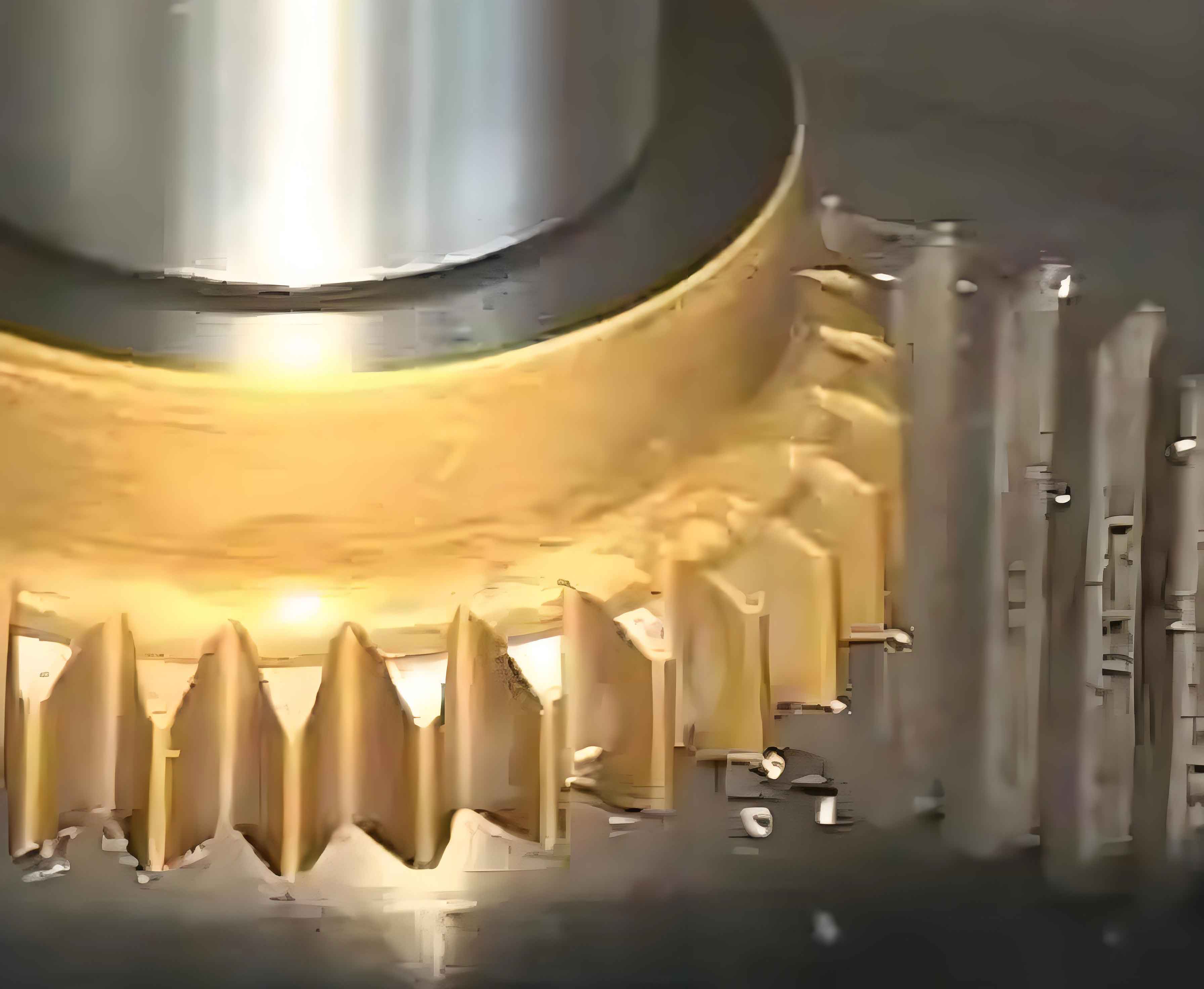
The core of the methodology lies in the two-degree-of-freedom point-grinding of the helical shaper cutter using a conical grinding wheel with axial reciprocation. The mathematical model for generating the cutter’s cutting edge is established based on the theory of gearing and the kinematic relationship between the grinding wheel and the cutter. The position vector of a point on the grinding wheel profile, defined in its own coordinate system, is transformed through a series of coordinate systems to ultimately describe the helical flank of the cutter and its intersection with the rake face, yielding the cutting edge. The coordinate transformation chain is critical and can be represented generically. Let $\mathbf{r}_w$ be the position vector of a point on the grinding wheel axial profile. Its representation in the shaper cutter coordinate system $\mathbf{r}_c$ is obtained through successive transformations:
$$ \mathbf{r}_c = \mathbf{M}_{cf} \mathbf{M}_{ft} \mathbf{M}_{tb} \mathbf{M}_{bw} \mathbf{r}_w $$
where $\mathbf{M}_{ij}$ are the homogeneous transformation matrices between coordinate systems. The corresponding normal vector $\mathbf{n}_c$ is transformed using the $3 \times 3$ rotational sub-matrices $\mathbf{L}_{ij}$:
$$ \mathbf{n}_c = \mathbf{L}_{cf} \mathbf{L}_{ft} \mathbf{L}_{tb} \mathbf{L}_{bw} \mathbf{n}_w $$
The cutting edge $\mathbf{r}_s$ is defined as the intersection curve of the cutter helical surface and its rake face, satisfying the equation $f(\phi_c, \theta_c)=0$, where $\phi_c$ and $\theta_c$ are surface parameters. This model allows for the calculation of the theoretical cutting edge and its deviation from a perfect involute.
To minimize the profile error of the shaper cutter across its effective re-sharpening depth, a multi-parameter correction of the grinding process is employed. The corrections target the grinding wheel profile and the generating motion. The modified axial profile of the conical grinding wheel can be expressed as a function of its profile parameter $u_w$, incorporating correction coefficients:
$$ x_w = u_w, \quad z_w = a_w u_w^2 + a_{ww} u_w^4 + d_s u_w + ( \alpha_{n0} + d_a) u_w $$
where $a_w$, $a_{ww}$, $d_s$, and $d_a$ are coefficients for parabolic correction, higher-order parabolic correction, profile translation, and pressure angle correction, respectively. $\alpha_{n0}$ is the nominal pressure angle. Furthermore, an additional generating motion $C_a$ is introduced as a function of the cutter rotation angle $\theta_c$ during grinding:
$$ C_a = c_1 \theta_c + c_2 \theta_c^2 + c_3 \theta_c^3 + c_4 \theta_c^4 $$
The optimal set of correction parameters $\mathbf{C}_w = [a_w, a_{ww}, d_s, d_a, c_1, c_2, c_3, c_4]$ is determined by minimizing the profile error across multiple re-sharpening layers. The profile error $\delta_e$ at a point on the cutting edge is calculated as the normal deviation from the reference involute:
$$ \delta_e = (\mathbf{r}_s – \mathbf{r}_{s0}) \cdot \mathbf{n}_{s0} $$
where $\mathbf{r}_{s0}$ and $\mathbf{n}_{s0}$ are the position and unit normal vectors of the reference involute surface. The optimization aims to minimize the root-mean-square of $\delta_e$ over the evaluated profile points and re-sharpening depths.
Grinding efficiency and surface roughness are paramount. The “equal-roughness” grinding method is adopted to determine the radial position and total number of the grinding wheel’s axial strokes. This method ensures a consistent theoretical cusp height (residual material) across the tooth flank, unlike constant radial increment or constant generating speed methods which lead to variable roughness. The radial position for each stroke $R_i$ is calculated iteratively to maintain a constant cusp height $\Delta$. The relationship between stroke index, radial position, and cusp height is governed by the local curvature and the grinding wheel geometry. A comparison of the theoretical cusp height for different methods given the same number of strokes clearly demonstrates the advantage of the equal-roughness approach.
| Grinding Method | Theoretical Cusp Height (µm) at Tip | Theoretical Cusp Height (µm) at Root | Max Variation |
|---|---|---|---|
| Radial Uniform Feed | 2.8 | 1.2 | 133% |
| Constant Generating Speed | 2.5 | 1.5 | 67% |
| Equal-Roughness (Target Δ=1µm) | 1.0 | 1.0 | ~0% |
The gear shaping process is modeled as a two-degree-of-freedom meshing between the shaper cutter and the workpiece gear. The primary motions are the rotation of the cutter $\phi_s$ and its axial feed $l_s$. To generate the correct helical gear, the workpiece must have a corresponding rotation $\phi_g$, which is nominally defined by the gear ratio and the lead. To facilitate topological modification, additional corrections are applied to the machine kinematics: a variable center distance $E$ and an additional workpiece rotation $C_b$. These are defined as polynomial functions of the process parameters:
$$ E = r_s + r_g + C_x, \quad C_x = a_0 + a_1 l_s + a_2 l_s^2 + a_3 l_s^3 + a_4 l_s^4 $$
$$ \phi_g = \frac{Z_s}{Z_g} \phi_s + \frac{l_s \tan \beta_g}{r_g} + C_b, \quad C_b = b_1 l_s + b_2 l_s^2 + b_3 \phi_s + b_4 \phi_s^2 + b_5 \phi_s l_s $$
where $r_s$, $r_g$ are pitch radii, $Z_s$, $Z_g$ are tooth numbers, $\beta_g$ is the workpiece helix angle, and $a_i$, $b_i$ are correction coefficients. The generated workpiece flank $\mathbf{R}_g$ is the envelope of the family of cutter cutting edge surfaces, defined by the meshing equation $\mathbf{N}_g \cdot \mathbf{V}_g^{(sg)} = 0$, where $\mathbf{N}_g$ is the normal to the workpiece surface and $\mathbf{V}_g^{(sg)}$ is the relative velocity.
The objective is to produce a gear with a specified target topological modification $\delta_m$ defined on the normal direction of the ideal involute surface $\mathbf{R}_1$. However, if an uncorrected shaper cutter is used in the standard gear shaping process, it will inherently produce a surface $\mathbf{R}_g^0$ with a certain error $\delta_g$. Therefore, the actual target surface for the corrected shaping process $\mathbf{R}_g^{m}$ must compensate for this inherent error. It is derived by subtracting the inherent shaping error from the desired modified surface:
$$ \mathbf{R}_g^{m} = \mathbf{R}_1 + \delta_m \mathbf{N}_1 $$
$$ \mathbf{R}_g^{0} = \mathbf{R}_1 + \delta_g \mathbf{N}_g^{0} $$
$$ \mathbf{R}_g^{m} \approx \mathbf{R}_g^{0} + \delta_{mg} \mathbf{N}_g^{0} \quad \Rightarrow \quad \delta_{mg} \approx (\mathbf{R}_g^{m} – \mathbf{R}_g^{0}) \cdot \mathbf{N}_g^{0} = (\delta_m \mathbf{N}_1 – \delta_g \mathbf{N}_g^{0}) \cdot \mathbf{N}_g^{0} $$
Here, $\delta_{mg}$ becomes the required normal modification to be generated by the corrected shaper cutter and corrected shaping kinematics, targeting the surface $\mathbf{R}_g^{0}$ as its new nominal.
The synthesis of the correction parameters is formulated as a sensitivity-based optimization problem. The required modification $\delta_{mg}$ at a point $i$ on the tooth flank can be linearly approximated as a function of all correction parameters (contained in vector $\boldsymbol{\zeta}$) through a sensitivity matrix $\mathbf{S}_i$:
$$ \delta_{mg}^{(i)} = \mathbf{S}_i \boldsymbol{\zeta} $$
Collecting equations for all $p$ evaluation points on the flank grid forms an over-determined system $\boldsymbol{\delta}_{mg} = \mathbf{S} \boldsymbol{\zeta}$. The vector $\boldsymbol{\zeta}$ combines parameters from both the cutter grinding and the shaping process: $\boldsymbol{\zeta} = [a_w, a_{ww}, d_s, d_a, c_1,…, c_4, a_0,…, a_4, b_1,…, b_5]^T$. The sensitivity matrix $\mathbf{S}$ is obtained by differentiating the workpiece surface equation with respect to each parameter in $\boldsymbol{\zeta}$. The optimal parameters are found by minimizing the sum of squared errors between the achieved and required modifications:
$$ \min F(\boldsymbol{\zeta}) = \sum_{i=1}^{p} \left( \delta_{mg}^{(i)} – \mathbf{S}_i \boldsymbol{\zeta} \right)^2 $$
A global optimization algorithm, such as a particle swarm optimization (PSO), is well-suited for solving this nonlinear problem, as it can handle the potential non-convexity introduced by the complex geometrical relationships in gear shaping.
A numerical case study demonstrates the effectiveness of the proposed methodology. The basic parameters of the helical gear set and the shaper cutter are listed below:
| Parameter | Shaper Cutter | Workpiece Gear | Grinding Wheel |
|---|---|---|---|
| Number of Teeth | 32 | 45 | – |
| Normal Module (mm) | 3 | 3 | – |
| Normal Pressure Angle (°) | 20 | 20 | 20 |
| Helix Angle (°) | 23 (Left Hand) | 23 (Right Hand) | – |
The optimization of the cutter grinding parameters successfully reduces the cutting edge profile error. The following table shows a subset of the optimized correction parameters for the left and right flanks of the shaper cutter:
| Flank | $a_w$ (×10⁻⁴) | $a_{ww}$ (×10⁻⁵) | $d_a$ (°) | $C_a$ Function |
|---|---|---|---|---|
| Left | 0.0 | 0.0 | +0.35 | -0.18($\theta_c$+0.087)² |
| Right | -0.5 | -0.7 | +0.31 | +0.128($\theta_c$-0.091)² |
For the gear shaping process, the target topological modification $\delta_m$ is defined as a combination of lead crowning and profile modification. The optimized shaping correction functions are high-order polynomials. For instance, the center distance correction for generating the right flank might be:
$$ C_x^{right} = 9.2 \times 10^{-4} + 1.25 \times 10^{-2} l_s + 1.04 \times 10^{-1} l_s^2 – 1.04 \times 10^{-3} l_s^4 $$
And the additional workpiece rotation correction could be:
$$ C_b^{right} = 5.64 \times 10^{-2} l_s + 8.9 \times 10^{-4} l_s^2 – 6.84 \times 10^{-3} \phi_s – 7.94 \times 10^{-5} \phi_s^2 $$
The final result of applying the fully corrected shaper cutter within the optimized gear shaping kinematics is a workpiece gear tooth flank that closely matches the target topological modification. The normal deviation between the simulated manufactured flank and the target flank is minimized across the entire active profile and face width. The maximum residual error is typically reduced to below 1-2 µm, demonstrating the high precision achievable with this comprehensive correction strategy. This methodology effectively addresses the historical limitations of gear shaping for precision finishing, unlocking its potential for manufacturing high-quality, topologically optimized gears, especially for complex geometries like internal gears where other processes are less feasible.