
The pursuit of higher performance, efficiency, and reliability in power transmission systems, particularly in demanding applications like automotive drivetrains, places stringent requirements on gear manufacturing quality. Among the critical components, hypoid gears are renowned for their ability to transmit motion between non-intersecting, perpendicular axes with high torque capacity and smooth operation. However, the complex geometry of hypoid gears presents significant challenges in achieving the desired surface finish and contact pattern after the primary grinding or cutting processes. Surface imperfections, including excessive roughness, can lead to premature failure modes such as wear, pitting, and noise generation. To address these issues and refine the tooth flank geometry, lapping is employed as a vital finishing process for hypoid gears.
Lapping is a low-cost, efficient abrasive finishing process where a pair of hypoid gears are run in mesh under a controlled load with an abrasive-laden compound (lapping fluid) introduced between the contacting flanks. The free abrasive particles within the compound remove minute amounts of material through a combination of rolling, sliding, and micro-cutting actions. This process helps in error averaging, improving contact pattern localization, reducing transmission error, and enhancing surface quality without damaging the hardened case layer. Despite its widespread industrial use, the lapping of hypoid gears has largely been governed by empirical knowledge and trial-and-error. The complex interaction between the abrasive particles and the non-conjugate, spatially curved tooth flanks makes it difficult to predict the resulting surface micro-topography—the intricate three-dimensional landscape of peaks and valleys that dictates functional performance.
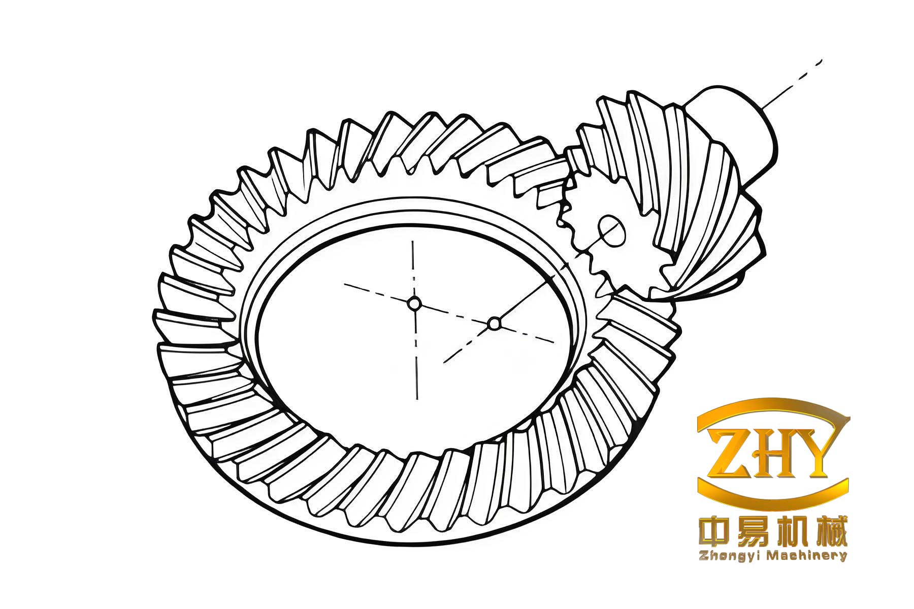
To bridge this knowledge gap and move towards a more scientific, predictive approach to process optimization, this work proposes a comprehensive methodology for predicting the surface micro-topography generated by the lapping of hypoid gears. The core of our approach lies in integrating the macroscopic meshing mechanics of the gear pair with the microscopic abrasive wear mechanisms. We begin by establishing a model for the lapping process, treating the complex point contact of hypoid gears as a series of discrete local interactions. For each discrete contact zone, we derive analytical expressions for the critical parameters governing abrasive action, most importantly the cutting depth of a single abrasive grain. This model accounts for the kinematics, applied load, material properties, and lapping fluid characteristics.
Subsequently, we develop a predictive algorithm that simulates the cumulative effect of numerous random abrasive passes over an initial surface topography (typically from the preceding grinding operation). By calculating the number of effective abrasive actions and the associated material removal at each point on the discretized tooth flank, we can predict the post-lapping surface height parameters. Finally, to visualize the predicted three-dimensional surface texture, we employ a surface reconstruction technique based on the Fast Fourier Transform (FFT). This allows us to generate a synthetic 3D surface micro-topography that statistically matches the predicted roughness parameters and exhibits the directional texture imparted by the relative sliding motion of the gear flanks. The validity of our model is demonstrated through a case study involving a commercial automotive drive axle hypoid gear set, showing good agreement between predicted and experimentally measured surface roughness parameters.
Theoretical Foundation: Modeling Abrasive Action in Hypoid Gear Lapping
The fundamental challenge in modeling lapping lies in scaling down from the gear pair level to the individual abrasive grain level. The contact between two hypoid gears is theoretically a point contact that evolves into an elliptical contact patch under load, as described by Hertzian contact theory. However, the presence of free abrasive particles and the non-conjugate motion significantly alter this contact. To render the problem tractable for micro-topography prediction, we adopt a discretized approach combined with mechanistic modeling of abrasive wear.
We discretize the theoretical contact ellipse on the tooth flank into a grid of sampling points. At each sampling point, the local contact conditions—including principal curvatures, contact pressure, and relative sliding velocity—are determined through Tooth Contact Analysis (TCA). The complex, non-conjugate interaction at each point is then conceptually simplified to an equivalent internal grinding model, where the abrasive particles act between two rotating curved surfaces.
The cornerstone of the material removal prediction is calculating the cutting depth (h) of a single abrasive grain. We model the abrasive grain as a conical indenter with a semi-apical angle $\varepsilon$. When a grain is trapped between the gear flanks under normal load $F_n$, it indents the surfaces. The depth of indentation is governed by the balance between the force on the grain and the resistance of the workpiece material, which undergoes plastic deformation. Based on principles of plasticity and indentation mechanics, the normal force on a single active grain can be related to its cutting depth and the material’s hardness $H$:
$$F_{n0} = \eta \xi H h_{max}^2 \tan \varepsilon$$
where $\eta$ is a constant (0~1), $\xi$ is a geometric factor (typically 2 for a cone), and $h_{max}$ is the maximum indentation depth at the trailing edge of the contact arc. The total normal force over the contact area is integrated from the forces on all active grains. By considering the contact area $A$, the number of active grains per unit area $N_d$, and the contact arc length $l_c$, the expression for the total normal force $F_n$ is derived. Relating this force to the contact stress (approximated by the material’s yield strength $\sigma_s$) over the grain-workpiece contact area $A_g = \pi h^2 \tan^2 \varepsilon / 2$, we can solve for the steady-state cutting depth $h$ of the grain:
$$h = \left[ \frac{0.51 \kappa \eta \xi H \left(1 + \frac{K (k_P – k_G)}{0.0127}\right) l_c}{\pi (k_P – k_G) \sigma_s N_d} \right]^{1/2}$$
In this equation, $k_P$ and $k_G$ are the principal curvatures of the pinion and gear at the contact point, respectively. $K$ is a correction factor accounting for the increase in effective contact area due to abrasive particles filling the gear backlash. $\kappa$ represents the proportion of total grains that are actively cutting. This formula establishes the direct link between process parameters (load, material properties, abrasive density) and the fundamental abrasive action.
The next critical step is estimating the number of times a given point on the tooth flank is subjected to this abrasive action during the total lapping time $t_s$. This depends on the lapping motion cycle. For a common straight-line reciprocating lapping path that moves the contact zone from toe to heel and back, any point on the flank will be lapped twice per full cycle. The number of lapping cycles $n_c$ is defined by the total time and the cycle period. The number of active grain engagements $n_l$ over a small surface area $S_l$ is therefore:
$$n_l = \kappa \frac{z_G n_G t_s}{n_c} S_l N_d$$
where $z_G$ and $n_G$ are the tooth number and rotational speed (RPM) of the gear, respectively. The term $N_d$, the number of active grains per unit area, is a function of the lapping fluid’s abrasive volume fraction $V$ and the average abrasive grain diameter $d$:
$$N_d = (0.1 \sim 0.5) \cdot \frac{6V}{\pi d^3}^{2/3}$$
With the cutting depth $h$ and the number of abrasive engagements $n_l$ determined, we possess the key inputs to simulate the cumulative material removal and predict the evolution of the surface topography.
The Micro-topography Prediction Model: A Four-Step Methodology
Our predictive model for the lapped surface of hypoid gears follows a systematic, four-step procedure that translates the theoretical abrasive mechanics into a quantifiable prediction of 3D surface texture.
Step 1: Calculation of Localized Cutting Depth. A finite element model or analytical TCA of the specific hypoid gears is used to compute the necessary contact parameters across the tooth flank. For each discrete sampling point on the flank grid, the local curvatures, contact pressure (from applied torque), and relative sliding velocity are extracted. These values are fed into Equation (3) to compute the local abrasive cutting depth $h$ for the given set of process parameters (lapping fluid specification, material hardness, load).
Step 2: Calculation of Localized Cutting Frequency. The lapping motion path must be defined. A typical path involves moving the contact zone between predefined points (e.g., toe, midpoint, heel) on the flank. Based on the total lapping time $t_s$, gear rotation speed $n_G$, number of teeth $z_G$, and the number of lapping cycles $n_c$, Equation (4) is used to calculate the number of abrasive engagements $n_l$ for each unit area of the flank. This accounts for the fact that different areas may experience different exposure times depending on the path.
Step 3: Iterative Material Removal Simulation. This step simulates the physical lapping process on a digital representation of the initial surface. The initial surface topography, usually obtained from a 3D measurement of a ground gear surface (with height matrix $Z_{initial}$), serves as the starting point. The simulation iterates for $n_l$ cycles. In each cycle, a simulated “abrasive grain” of width $b$ (related to $h$ and $\varepsilon$) engages with the surface at a random starting location along the direction of relative sliding. The algorithm scans the height profile under this contact width and removes material by an amount equal to the cutting depth $h$, but only from the highest peaks within that width, simulating a leveling or filtering action. The condition for removal is that a peak’s height must be above a threshold defined by the surrounding valley heights plus the cutting depth. After each simulated pass, the surface height matrix is updated. This iterative process continues until the total number of engagements $n_l$ is completed, resulting in a final predicted height matrix $Z_{predicted}$ from which statistical height parameters like $S_a$ (arithmetic mean height) and $S_q$ (root mean square height) are computed.
| Parameter Category | Symbol | Description |
|---|---|---|
| Gear Geometry & Kinematics | $k_P, k_G$ | Principal curvatures at contact point |
| $v_P, v_G$ | Surface velocities at contact point | |
| $z_G, n_G$ | Gear tooth number and rotational speed | |
| Process Parameters | $T$ | Applied lapping torque |
| $t_s$ | Total lapping time | |
| $n_c$ | Number of lapping path cycles | |
| Path | Definition of contact zone movement | |
| Lapping Fluid & Abrasive | $V$ | Abrasive volume fraction in fluid |
| $d$ | Average abrasive grain diameter | |
| $\varepsilon$ | Abrasive grain semi-apical angle | |
| Workpiece Material | $H$ | Material Hardness |
| $\sigma_s$ | Yield Strength | |
| Initial Surface | $Z_{initial}$ | 3D height matrix of pre-lapped surface |
Step 4: Surface Micro-topography Reconstruction. While Step 3 yields statistical parameters, a visual 3D representation is valuable for analysis. We employ an FFT-based surface reconstruction technique to generate a synthetic surface $Z_o$ that matches the predicted statistics and spatial characteristics. The inputs for reconstruction are derived from $Z_{predicted}$: the height parameters ($S_q$, skewness $S_{sk}$, kurtosis $S_{ku}$), the autocorrelation lengths ($\tau_x$, $\tau_y$) which describe texture spacing, and the texture lay angle $\theta$ (determined from the direction of the relative sliding velocity vector). The algorithm works by generating a random height field with a specified power spectral density (PSD) and then iteratively transforming its height distribution to match the target $S_{sk}$ and $S_{ku}$ using the Johnson translation system. The final reconstructed surface $Z_o$ provides a realistic visualization of the predicted lapped surface of the hypoid gears.
The core equations for the FFT-based reconstruction are summarized below:
1. Generate a random matrix $\mathbf{R}$ with Gaussian distribution: $\mathbf{R} = \text{ifft2}(2 e^{i 2\pi \mathbf{\Phi}})$, where $\mathbf{\Phi}$ is a uniform random matrix.
2. Compute the transfer matrix $\mathbf{K}$ from the target autocorrelation function $\mathbf{C_z}$: $\mathbf{K} = \text{ifft2}(\text{fft2}(\mathbf{C_z})^{\circ1/2} \odot |\text{fft2}(\mathbf{R})| )$.
3. Generate an initial surface $\mathbf{Z_s}$ with target PSD: $\mathbf{Z_s} = \text{ifft2}(\text{fft2}(\mathbf{K}) \circ \text{fft2}(\mathbf{R}))$.
4. Iteratively adjust the height distribution of $\mathbf{Z_s}$ to match the target $S_{sk}$ and $S_{ku}$ using acceptance-rejection sampling and power spectrum preservation techniques.
Case Study, Validation, and Parametric Analysis
To demonstrate and validate the model, we applied it to a hypoid gear set from an automotive drive axle. The basic design parameters of the gear set are listed in Table 2.
| Parameter | Pinion | Gear |
|---|---|---|
| Number of Teeth | 10 | 37 |
| Module (mm) | 8.4717 | |
| Pressure Angle (°) | 22.5 | |
| Shaft Offset (mm) | 30 | |
| Hand of Spiral | Left | Right |
The lapping process parameters were: gear speed $n_G = 400$ rpm, lapping torque $T = 8-12$ Nm, lapping time $t_s = 150$ s. The lapping fluid contained 240-mesh green silicon carbide abrasive with a oil-to-abrasive weight ratio of 1.3:1. The initial surface topography of the gear convex flank was measured via white-light interferometry. Using our model, we predicted the post-lapping surface. The predicted key height parameters from multiple simulation runs were averaged and compared with the actual measured values from a physically lapped gear (same parameters). The comparison is shown in Table 3.
| Parameter | Experimental Value | Predicted Value (Avg. of 3 runs) | Maximum Error |
|---|---|---|---|
| Arithmetic Mean Height, $S_a$ (μm) | 1.1272 | 1.1457 | 2.49% |
| Root Mean Square Height, $S_q$ (μm) | 1.4810 | 1.4778 | 0.73% |
| Skewness, $S_{sk}$ | -0.6635 | -0.6825 | 4.73% |
| Kurtosis, $S_{ku}$ | 4.8321 | 4.6372 | 4.82% |
The agreement between prediction and experiment is very good, with all errors below 5%. This validates the model’s capability to reliably predict the outcome of the lapping process for hypoid gears in terms of surface roughness metrics.
Leveraging the validated model, we conducted a systematic parametric analysis to understand the influence of key process variables on the resulting surface roughness ($S_a$). The baseline parameters were: $N_d = 100$ grains/mm², $d = 30 \mu m$, $\varepsilon = 60^\circ$, $T=3$ Nm, $n_G=400$ rpm. One parameter was varied at a time while others were held constant.
1. Abrasive Grain Density ($N_d$): Simulating different lapping fluid concentrations, we found that $S_a$ decreases sharply as $N_d$ increases from low values, then gradually stabilizes. This is because with more grains sharing the load, the cutting depth per grain decreases, leading to a finer, more uniform finish. Beyond a saturation point, adding more grains yields no further benefit.
2. Abrasive Grain Size ($d$): The relationship between grain size and roughness showed a general positive correlation but with some stochastic scatter inherent to the process. Larger grains tend to produce deeper scratches and greater material displacement, increasing $S_a$.
3. Workpiece Material Hardness/Yield Strength ($\sigma_s$): Increasing material yield strength (simulating a harder material or a harder abrasive) leads to a decrease in predicted $S_a$. Harder materials resist plastic deformation and deep indentation by the abrasive grains, resulting in shallower cutting depths and a smoother final surface.
4. Applied Lapping Torque ($T$): Increased torque, which raises the normal contact force, leads to a proportional increase in $S_a$. Higher forces drive grains deeper into the surface, causing more aggressive cutting and ploughing, which roughens the surface rather than polishing it. This indicates that for finishing, a moderate to low torque is preferable.
5. Gear Rotational Speed ($n_G$): The effect of speed is non-monotonic. At very low speeds, lapping may be incomplete. As speed increases, $S_a$ initially rises slightly (possibly due to more energetic impacts) but then trends downward. Higher speeds increase the number of abrasive engagements per unit time ($n_l$), promoting a more uniform, polished finish through a higher frequency of finer scratches.
To quantify the relative influence of the abrasive-related parameters, an orthogonal design and analysis of variance (ANOVA) was performed focusing on $N_d$, $d$, and $\sigma_s$. The results, summarized in Table 4, clearly show that the number of active grains per unit area ($N_d$, dictated by fluid concentration) is the most significant factor affecting lapped surface roughness, followed by material hardness. The abrasive grain size ($d$) had a comparatively smaller statistical effect within the tested range.
| Factor | Degrees of Freedom (df) | Contribution to Variance | Relative Significance |
|---|---|---|---|
| Grain Density ($N_d$) | 2 | 22.65% | Most Significant |
| Workpiece Yield Strength ($\sigma_s$) | 2 | 10.51% | Significant |
| Grain Diameter ($d$) | 2 | 1.32% | Less Significant |
| Error / Other Factors | 2 | 65.53% | – |
Conclusion
This work has presented a novel and effective methodology for predicting the surface micro-topography generated during the lapping of hypoid gears. The model successfully integrates the macroscopic kinematics and contact mechanics of the gear pair with a mechanistic description of microscopic abrasive wear. By deriving the cutting depth of a single abrasive grain under the specific contact conditions of hypoid gears and simulating the cumulative, random nature of the abrasive process on a digital surface, we can accurately predict post-lapping surface roughness parameters such as $S_a$ and $S_q$. The integration of an FFT-based surface reconstruction technique further allows for the visualization of the predicted 3D surface texture, providing insights beyond scalar parameters.
The validation against experimental data from an automotive hypoid gear set confirmed the model’s reliability, with prediction errors for key height parameters remaining below 5%. The subsequent parametric analysis delivered valuable practical insights: the concentration of abrasive in the lapping fluid (affecting $N_d$) is the most influential factor for controlling surface finish, highlighting the critical role of fluid formulation. Process parameters like torque and speed require careful optimization, as excessive torque increases roughness, while higher speeds generally promote a smoother finish after an initial transition zone.
The proposed model offers a powerful tool for virtual process optimization, reducing the reliance on costly and time-consuming physical trials in the development of lapping processes for hypoid gears. Future work could focus on incorporating more detailed abrasive wear mechanisms (e.g., fracture, attritious wear), modeling the dynamics of the lapping machine, and extending the surface reconstruction to cover the entire active tooth flank for a holistic analysis of the lapped hypoid gears surface.